Build and flash your first nRF Connect SDK application
In this exercise, we will program a simple application based on the blinky sample to toggle an LED on our board. Again, any supported Nordic Semiconductor development board will work (nRF54, nRF53, nRF52, nRF70, or nRF91 Series). The idea is to make sure that all the tools needed to build and flash a sample are set up correctly. The focus is to learn how to create an application from a template “Copy a sample”, build the application, and flash it on a Nordic-powered board.
Basically, we will walk you through the three bullet points below:
- Create a new application based on a template(sample).
- Build an application.
- Flash an application to a board.
Exercise steps
1. Create a folder close to your root directory. This will hold all the exercises that we will be working on throughout this course.
We will create that folder on the C drive in C:\myfw\ncsfund. Avoid storing your applications in locations with long paths, as the build system might fail on some operating systems (Windows) if the application path is too long. Also, avoid using whitespaces and special characters in the path.
2. In VS Code, click on the nRF Connect Extension icon. In the WELCOME View, click on Create a new application.

3. In the Create new application, select Copy a sample . Then select the SDK version you plan to use.

In the Create new application, you will be presented with three options: Create a blank application , which will create a blank application with an empty main() function. While the Copy a sample will present you all the templates “samples” that come from the different modules in nRF Connect SDK and enable you to create an application based on a template. Note that if you have multiple SDK versions installed on your machine, you will be prompted to select which SDK version to copy a sample from. The Browse nRF Connect SDK Add-on index (out of scope for this course) is to copy a revision of an existing out-of-tree application compatible with the nRF Connect SDK from the online application index and set up a west workspace repository around it.
Definition
The SDK contains a rich set of templates. In the context of templates:
Samples are simple and showcase a single feature or library (e.g. SHA256 sample, UART sample, PWM sample, blinky sample, etc..)
Applications are complex and include a variety of libraries to implement a specific use case (e.g. Asset tracker application, Keyboard application, Mouse application).
3.1 Type blinky in the search field and select the second Blinky sample (with the path zephyr/samples/basic/blinky) like below.
The Blinky sample blinks LED1 (LED0 on nRF54 DKs) on your board indefinitely.

We will base our first application on the Blinky sample. The Blinky sample comes from the Zephyr module in nRF Connect SDK, which is why you see the zephyr name in the sample path: zephyr\samples\basic\blinky .
Through the icons  , we can access the in-tree sample (inside the SDK installation directory), online documentation of the sample, and the GitHub of the sample, respectively.
Through the icons , we can filter samples/applications based on the module they come from (nrf, zephyr ,etc..) and supported hardware. Note that the supported hardware is not always accurate as it relies on samples explicitly listing the supported hardware, which is not the case for all samples.
3.2 Input the full path for where you want the application to be stored.
1. Select where you want to store your application. Input the directory you created in step 1 (for example: C:\myfw\ncsfund\).

2. Name your application l1_e2. This is the naming convention we will use for exercises throughout this course. Note that this will create a folder for your application called l1_e2.

When you have input the full path, press enter.
VS Code will ask if you want to open the application in the same VS Code instance or open a new VS Code instance. Select Open to open the application in the same VS Code instance.

This will make a copy of the template selected “Blinky sample”, store it in the application directory you specified, and add an unbuilt application to VS Code as shown below:

Note
nRF Connect for VS Code might show error squiggles indicating header files not found for an unbuilt application. These usually appear in the PROBLEMS tab. Please ignore these error squiggles at this stage. These errors will automatically be resolved once you add and build a configuration (next step).
4. Add a build configuration.
One of the many advantages of the nRF Connect SDK is the high decoupling between the application source code and the software configuration/hardware description, making it extremely easy to switch the build for a new hardware or software configuration.
This step will specify which development board or custom board (hardware) we want to build the application for. We will also select the software configuration (*.conf and possible devicetree overlays) to be used in the build.
What you set in the Add Build configuration controls what is passed to the underlying command-line tool, west.
In the APPLICATIONS view, click on Add Build Configuration under the application name.

This will open the Add Build Configuration window shown below:
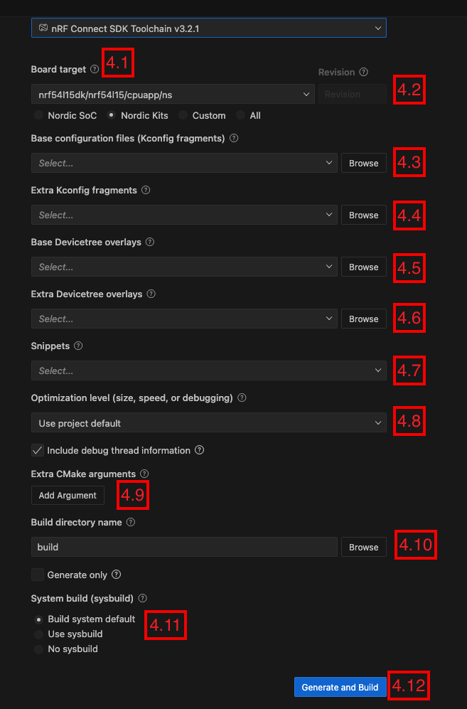
The first thing to notice is that the GUI will inform you about the SDK/toolchain version that will be used to build the application. Ensure it corresponds to the SDK/toolchain you intend to use, along with the SDK version from which you copied the sample from. If it doesn’t, click the arrow to select the correct version.
4.1. Using the Board target, choose the board you want to flash your application to. See the table below for an overview of board targets for Nordic devices.
| Device | Board target |
|---|---|
| nRF54LM20 DK* | nrf54lm20dk/nrf54lm20a/cpuapp |
| nRF54LS05 DK* | nrf54ls05dk/nrf54ls05b/cpuapp |
| nRF54L15 DK* | nrf54l15dk/nrf54l15/cpuapp/ns |
| nRF5340 DK | nrf5340dk/nrf5340/cpuapp/ns |
| nRF52840 DK | nrf52840dk/nrf52840 |
| nRF52833 DK | nrf52833dk/nrf52833 |
| nRF52 DK | nrf52dk/nrf52832 |
| nRF9160 DK | nrf9160dk/nrf9160/ns |
| nRF9161 DK* | nrf9161dk/nrf9161/ns |
| nRF9151 DK* | nrf9151dk/nrf9151/ns |
| Thingy:91 X | thingy91x/nrf9151/ns |
| Thingy:91 | thingy91/nrf9160/ns |
| Thingy:53 | thingy53/nrf5340/cpuapp/ns |
| nRF7002 DK* | nrf7002dk/nrf5340/cpuapp/ns |
*The nRF54LM20 DK is supported in nRF Connect SDK v3.1.1 and higher.
*The nRF54LS05 DK is supported in nRF Connect SDK v3.3.0 preview2 and higher.
*The nRF54L15 DK and the Thingy:91 X are supported in nRF Connect SDK v2.8.0 and higher.
*The nRF7002 DK and nRF9161 DK are supported in nRF Connect SDK v2.5.0 and higher.
*The nRF9151 DK is supported in nRF Connect SDK v2.6.0 and higher.
In the screenshot, we chose the nRF54L15 DK by specifying its board target, nrf54l15dk/nrf54l15/cpuapp/ns
4.2. The board Revision is usually written on a sticker on the board with the format X.X.X. However, this field is optional and only applicable if the board has multiple revisions (like the nRF9160 DK). By setting it to blank, the build system selects the default version set in the board definition.
We will keep the default build configuration for the rest. However, it’s important to understand the role of each of these configurations.
4.3. The Base configuration files. Depending on the template you chose in Step 3, you will be presented with at least one base application configuration file prj.conf. Some templates contain more than one application configuration file (eg: prj.conf, prj_minimal.conf, prj_cdc.conf). These different configurations, if found in the template, are explained in the template documentation. The blinky template has only one option. This is equivalent to FILE_SUFFIX (and CONF_FILE) in west . prj.conf will be selected by default
4.4. The Extra Kconfig fragments field will list the Kconfig fragments available in the template or added to the application folder. These are modifiers to the application configuration file (covered in Lesson 3). The blinky template has none. This is equivalent to EXTRA_CONF_FILE in west .
4.5. The Base Devicetree overlays field will list the Devicetree overlays that are available in the template or have been added to the application folder. These are modifiers to your hardware description (covered in Lesson 3). The blinky template has none. This is equivalent to DTC_OVERLAY_FILE in west .
4.6. The Extra Devicetree overlays. It provides additional, custom devicetree overlay files to be “mixed in” with the base devicetree overlay file This is equivalent to EXTRA_DTC_OVERLAY_FILE in west .
4.7 The Snippets. Snippets combine both software configuration (Kconfig) and hardware configuration (Devicetree) in one bundle. There are several snippets in the SDK.
4.8 Optimization level(size, speed, or debugging). We have four options here.
- Use project default: Use the project default settings set in the application configuration file
(prj.conf) , the application configuration file is covered in Lesson 3. - Optimize for size (-Os): This will pass the following Kconfig to the build system
CONFIG_SIZE_OPTIMIZATIONS="y" - Optimize for speed(-O2): This will pass the following Kconfig to the build system
CONFIG_SPEED_OPTIMIZATIONS="y" - Optimize for debugging (-Og): This is important to set if you plan to debug your application and use the RTOS-aware debugger in nRF Connect for VS Code. Selecting this option in the GUI will pass the following Kconfig symbol to the build system
CONFIG_DEBUG_OPTIMIZATIONS="y"
The Include debug thread information when checked will pass the CONFIG_DEBUG_THREAD_INFO to the build system. You can see thread information in the Debugger Thread Viewer, but only if you also select the Optimize for debugging(-Og) optimization level.
4.9. TheExtra CMake arguments field allows you to pass arguments to the build system if needed. We will leave that blank for this demo.
4.10 The Build directory name field gives you the option to manually name the build directory where the final binary files and temporary build files will be stored. We will leave this to be the default name specified by the tool, which is build or build_1 if you have already built one application before.
In this exercise, we will leave the option to Use project default. However, it’s important to remember to use Optimize for debugging (-Og) if you plan to debug your application.
Leave the Generate only option disabled to trigger the build process after clicking the Build Configuration button.
4.11 Starting from nRF Connect SDK v2.8.0, Sysbuild is enabled by default. Sysbuild is of importance when your application has multiple images. Leave this option to the default value of Build system default
4.12 Click the Generate and Build button to create the configuration and initiate the build process.
The build process will take some time to finish. Open the nRF Connect Terminal (View->Terminal) to see the progress of the build.
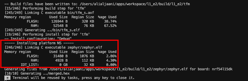
A successful build is indicated by displaying the application’s memory usage, as shown in the screenshot above.
A key component in the build process is west, which is a core command-line utility in nRF Connect SDK/Zephyr.
west provides several services like repository management, building applications, and flashing, and is internally invoked by nRF Connect for VS Code. You can also issue these commands manually in the command line prompt if you prefer to work in the terminal
Make sure to select nRF Connect Terminal, as shown in the screenshot below as this is the terminal where the toolchain is sourced. Step 1 – Open nRF Connect Terminal, Step 2 – Type west help if you are interested in learning how to use the command-line interface with the nRF Connect SDK.

Note that the nRF Connect Terminal will open for the active toolchain/SDK used to build the application. You can also open nRF Connect Terminal from the Manage toolchains -> Open Terminal Profile.
Alternatively, you can checkout this short video or read the documentation of west available here.
If you switch to the Explorer in VS Code or browse to the application directory, you will notice that there is a new sub-directory created from the build process called build . This folder contains the build output including the binary file that we will flash on the board in the next step.

5. Make sure that your development kit is connected to your computer and that it is switched on. It should be listed in the Connected Devices View in the nRF Connect for VS Code extension.
Important
If you are using a Thingy (Thingy:53, Thingy:91 X, or Thingy:91), they do not have an onboard debugger) so the flash procedure is different, and the device will not show up under Connected Devices View in the nRF Connect for VS Code extension. Skip steps 5 and 6, and please go through the flash procedure for the Thingy:53 here and for the Thingy:91 X or Thingy:91 here.

If you don’t see your board listed, press the Refresh Connected Devices icon  in the Connected Devices View.
6. From the Actions View, click Flash to flash the application to the board. You can open the Terminal Panel to see the progress of the flashing, as shown below.

Note
The difference between Flash and Erase And Flash To Board is that the latter erases the whole device, including all data the application has saved.
For example, if the device is added to a mesh network, Erase And Flash To Board will make the device forget this.

Early access program
Early Access Program for the nRF54LS05 DK
You need the latest nrfutil device command (v2.17.2 or higher) to flash the nRF54LS05 DK. To update the device command, run nrfutil upgrade device
LED1 (LED0 on nRF54 DKs)on your board should be blinking now in one second intervals.

Note
On the nRF54L Series DK, the board’s LEDs are labeled with PCB labels (PCB silkscreen) that start with 0 (LED0-LED3). In previous-generation development kits, the indexing starts with 1 (LED1-LED4). So, running the above sample on the nRF54L Series DK will make LED0 blink.
7. Just for the sake of this demonstration, let’s change the LED blink rate.
Locate the main.c file in Source Files->Applications or through the Explorer View of Visual Studio Code. On line 11, change the value of the SLEEP_TIME_MS from 1000 to 100. This will change the interval at which the LED is blinking.
#define SLEEP_TIME_MS 1008. Rebuild and re-flash the application on your board. You should observe that the LED is now blinking at a higher frequency.
In Lesson 2, we will take an in-depth look at the source code of this application to understand how it works.

