In this exercise, we will learn how to perform DFU over UART. First, we will enable Serial Recovery, and then we will add DFU from the application functionality. Both of these can be active at the same time, as the bootloader operates independently from the application.
| Serial Recovery | DFU from the application |
|---|---|
| ✅ Simplicity: Easier to implement since it only involves the bootloader. ✅ Single slot support: Can use a single slot for firmware updates, reducing flash memory requirements. ✅ Reliability: The user can always recover if the application fails since the bootloader has DFU capabilities. ❌Limited features: Only supports basic recovery functions, lacking advanced wireless transports such as Bluetooth LE. ❌Manual DFU mode activation: Requires the user to have physical access to the device and manually put into DFU mode (e.g., by pressing a button or using a jumper). | ✅ Flexibility: Can support more advanced features, such as wireless transport (e.g., Bluetooth LE, Wi-Fi, cellular IoT), image compression, etc. ✅ Better user experience: Provides a more user-friendly experience and does not require manual DFU mode activation. It also gives possibility to implement remote firmware upgrade. ✅ Seamless updates: Allows for updates to be performed in the background while the application is running, minimizing downtime. ❌Increased complexity: Requires additional development effort to implement robust update mechanisms. ❌Dual slot requirement: A dual-slot setup is necessary to recover from a corrupted DFU attempt. |
UART0 on our development kits are routed to the debugger chip and exposed to the connected PC as a VCOM port. Therefore, we do not have to connect anything extra to the DK to test DFU over UART.

Exercise prerequisites
To send firmware updates via UART, we will use a desktop tool called AuTerm. For alternative tools, check out this page.
Install AuTerm by following its downloading and Setup README. Pre-release builds are available for Windows, MacOS, and Linux from the releases page (Expand assets).

In AuTerm, select the Config tab first (1). As the initial configuration step, change the Config Port Settings to the port the DK is connected to (2).
Note that the port number will vary from machine to machine and DK to DK. Use the Connected Devices view in nRF Connect for VS Code to know the port of your DK.

We will extensively use the MCUmgr tab (3) in this exercise.
Prepare the DK
This is not a required but a recommended step. The DK debugger (Interface MCU)has a virtual mass storage disk. This may interfere with UART DFU transfer since the Interface MCU is also used for UART<> USB conversion, so it is recommended to disable it using the J-link Commander(Windows), or JLinkExe(Linux) :
JLinkExe -device NRF52840_XXAA -if SWD -speed 4000 -autoconnect 1 -SelectEmuBySN SEGGER_ID
J-Link>MSDDisable
Probe configured successfully.
J-Link>exitThe Development Kit must then be power-cycled for the settings to take effect. Replace SEGGER_ID with the SEGGER ID of your DK. The SEGGER ID is for the on-board debugger on the DK. Each DK has its unique SEGGER ID. The SEGGER ID is displayed in the Connected Devices View in nRF Connect for VS Code, as shown in the screenshot below. It’s also printed on the kit label.

Note that this setting remains valid even if you program another firmware onto the device.
Exercise steps
For this exercise, The base code is simply a copy of the Blinky sample. The goal here is to show you how to add MCUboot to an existing nRF Connect SDK application.
Open the code base of the exercise by navigating to Create a new application in the nRF Connect for VS Code extension, select Copy a sample, and search for Lesson 9 – Exercise 1.
Alternatively, in the GitHub repository for this course, go to the base code for this exercise, found in l9/l9_e1.
1. Enable MCUboot.
1.1 In sysbuild.conf add the below line to enable MCUboot
# STEP 1.1 - Enable MCUboot
SB_CONFIG_BOOTLOADER_MCUBOOT=y1.2 By default, MCUboot splits the non-volatile memory into two slots. Since we will use Serial Recovery in this exercise, we can use only one slot instead to get more available non-volatile memory. We can do this by setting SB_CONFIG_MCUBOOT_MODE_SINGLE_APP.
# STEP 1.2 - Configure bootloader to use only one slot.
SB_CONFIG_MCUBOOT_MODE_SINGLE_APP=y2. Enable logging for MCUboot.
2.1 Create a sysbuild/ directory to configure child images.
2.2 Create a file to configure MCUboot in the child image folder and add the following comments inside mcuboot.conf
# STEP 2.3 - Enable logging for MCUboot

# STEP 3.1 - Enable Serial Recovery over UART

# STEP 3.2 - Disable UART, since Serial Recovery uses it

# STEP 3.3 - Turn on a LED so we can see when Serial Recovery mode is activeThe folder structure should now look like this:

2.3 Next, we will enable logging for MCUboot. For this, we both need to enable logs and set the log level:
CONFIG_LOG=y
CONFIG_MCUBOOT_LOG_LEVEL_INF=yAfter this, we can build and run the sample to see it run with MCUboot. Observe logs from nRF Serial Terminal:
*** Booting MCUboot v2.1.0-dev-12e5ee106034 ***
*** Using nRF Connect SDK ***
*** Using Zephyr OS v3.7.99-1f8f3dc29142 ***
I: Starting bootloader
I: Bootloader chainload address offset: 0xc000
*** Booting My Application v0.0.0 - unknown commit ***
*** Using nRF Connect SDK v2.9.0-7787b2649840 ***
*** Using Zephyr OS v3.7.99-1f8f3dc29142 ***Important
On the nRF7002 DK only, ensure that the SPI NOR driver is disabled by default by adding the following lines in sysbuild/mcuboot.conf
CONFIG_SPI=n
CONFIG_SPI_NOR=n
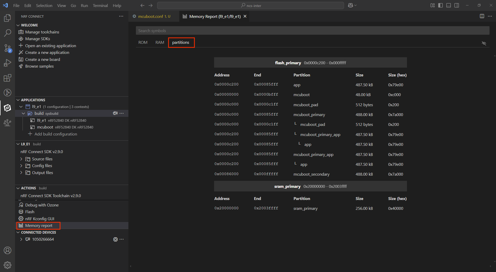
We can also see the partitioning of the device, with the nRF Connect for VS Code Memory Report

Side note: Without the SB_CONFIG_MCUBOOT_MODE_SINGLE_APP=y, you will have two slots mcuboot_primary and mcuboot_secondary as shown below:
Now, we have MCUboot running before the application. However, we can not yet update the application.
3. Add DFU over UART to MCUboot.
Next, we will add DFU over UART to MCUboot, also known as Serial Recovery. MCUboot configuration options can be found here, and MCUboot Kconfig options specific for Serial Recovery are found here.
3.1 To enable Serial Recovery, we must set CONFIG_MCUBOOT_SERIAL and to enable transport over UART, we must set BOOT_SERIAL_UART. Since these are both for the MCUboot child image, we must set them in mcuboot.conf.
CONFIG_MCUBOOT_SERIAL=y
CONFIG_BOOT_SERIAL_UART=yImportant
If you are developing for the nRF54L15 DK, be sure to increase the space allocated for MCUboot by adding the following line to your mcuboot.conf file: CONFIG_PM_PARTITION_SIZE_MCUBOOT=0xF000. The value 0xF000 was chosen somewhat arbitrarily, so remember to optimize this size for your specific project.
3.2 Since we now use UART for Serial Recovery, we must disable UART from the console from MCUboot, so this does not try to use the UART at the same time.
CONFIG_UART_CONSOLE=n3.3 To indicate that MCUboot is in Serial Recovery mode, it is nice to have an indicator LED. We can enable this by setting CONFIG_MCUBOOT_INDICATION_LED.
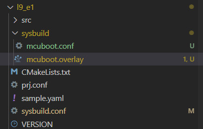
CONFIG_MCUBOOT_INDICATION_LED=y3.4 We will set which button and LED will be used before testing. This is set using a Devicetree overlay. For this, we will create the file sysbuild/mcuboot.overlay. Now, the folder structure will then look like this:
Add the following comment to mcuboot.overlay:
/* Step 3.4 - Configure button and LED for Serial Recovery */Under it, add
/ {
  aliases {
		mcuboot-button0 = &button1;
		mcuboot-led0 = &led1;
  };
};Note that the alias button1 represents the physical Button 2 on the DK (all Nordic DKs, except nRF54L15 DK). led1 alias represents the physical LED2 on the DK. Aliases and node identifiers in devicetree start from 0, while on the physical board, they start from 1.
Note
On the nRF54L15 DK, the aliases button1 and led1 actually refer to Button 1 and LED1. Since the PCB labels on that DK start from 0.
Test Serial Recovery
4. Build and flash the application to your board.
Note
In nRF Connect SDK v2.9.0, you can get the following warning during the build process:
warning: UPDATEABLE_IMAGE_NUMBER (defined at ... was assigned the value '1' but got the value ''. ...
warning: MCUBOOT_UPDATE_FOOTER_SIZE (defined at subsys/dfu/Kconfig:54) was assigned the value
'0x2000' but got the value ''. ...
While it is, in general, good practice to fix Kconfig Override Warnings, you can safely ignore this one as MCUBOOT_IMG_MANAGER is not mandatory for Serial Recovery.
Now we can test Serial Recovery. When you start the kit normally, you see LED1 blink as normal (main).
4.1 Now, hold button 2 (button 1 on the nRF54L15 DK) while resetting the Development Kit. Instead of starting normally, the kit will now enter Serial Recovery mode. You can see this from LED2 (LED1 on the nRF54L15 DK), which should be on.
4.2 While in serial recovery mode, we can use AuTem to communicate with the DK. Navigate to the MCUmgr tag. Here you can see SMP command Groups in the left vertical tabs. Click “Connect” to Connect to the DK. You should see the UART port number and settings printed in the bottom bar.
4.3 With this configuration, we can test listing current images on the DK. Click Images -> Get -> Go to list images:
4.4 Change something in the application to verify that the new firmware image has been flashed.
Before we try to upload a new firmware image to the DK, we should change something in the application, so we can verify that the new firmware image has been flashed. This can, for example be to change the delay in the blinky code. For example, change SLEEP_TIME_MS in main.c from 1000 to 100, then rebuild the code. Do not flash it using the Debugger.
4.5 Upload the new image firmware to the DK.
Now we can upload the new image firmware to the DK, using the Upload tab. From Update files, we see that we can use build/l9_e1/zephyr/zephyr.signed.bin, which is the signed image Sysbuild has automatically generated for us.
Use the “No action”. Since Serial Recovery does not use Swap, we do not need to use “Test” or “Confirm”.
4.6 After the successful upload, reset the DK to see the new image in effect. The video above also shows how to reset the DK over SMP, but you can also use the reset button if you want.
DFU over UART from the application
5. Add DFU over UART to the application.
Next up, we will add DFU over UART to the application. This method uses the mcumgr library.
5.1 First, we must go back to dual slots, as DFU from the application must have two slots. Change SB_CONFIG_MCUBOOT_MODE_SINGLE_APP from y to n in sysbuild.conf. Or simply comment out the line, as the default mode is dual slot.
SB_CONFIG_MCUBOOT_MODE_SINGLE_APP=n5.2 Then we add mcumgr configurations and dependencies to the application configuration file (prj.conf). We can take inspiration from the SMP Server sample to find which configurations we need.
For this exercise, we can use the following Kconfigs in prj.conf
# STEP 5.2 - Enable mcumgr DFU in application
# Enable MCUMGR
CONFIG_MCUMGR=y

# Enable MCUMGR management for both OS and Images
CONFIG_MCUMGR_GRP_OS=y
CONFIG_MCUMGR_GRP_IMG=y

# Configure MCUMGR transport to UART
CONFIG_MCUMGR_TRANSPORT_UART=y

# Dependencies
# Configure dependencies for CONFIG_MCUMGR
CONFIG_NET_BUF=y
CONFIG_ZCBOR=y
CONFIG_CRC=y

# Configure dependencies for CONFIG_MCUMGR_GRP_IMG
CONFIG_FLASH=y
CONFIG_IMG_MANAGER=y

# Configure dependencies for CONFIG_IMG_MANAGER
CONFIG_STREAM_FLASH=y
CONFIG_FLASH_MAP=y

# Configure dependencies for CONFIG_MCUMGR_TRANSPORT_UART
CONFIG_BASE64=y
5.3 Build and flash the application to the DK.
With this, we can do DFU over UART without entering bootloader mode manually.
Build, flash, and start the DK normally (do not hold any buttons). Now, we can use AuTerm to list images, as before:
Then we change the application code again. Also, increment VERSION_MINOR in the VERSION file. We will be able to see the version in AuTerm.
VERSION_MAJOR = 0
# STEP 5.3 - Increment minor version
VERSION_MINOR = 1
PATCHLEVEL = 0
VERSION_TWEAK = 0
EXTRAVERSION = Pristine build the code (Do not flash using the Debugging) and upload the new firmware image using AuTerm.
The “image number” that you can choose here should stay at 0. If you got another pair of primary/secondary slots, the next pair would be image 1, and so on. An example of this will be when we update the network core on the nRF5340, which we will see in a later exercise.
Select “Test” to tag the image as “test” after the upload:
5.4 Since we now use a dual slot configuration, an image tagged as “test” will initiate a swapon next reboot. Check Slot 1 in the image list in AuTerm.

Then reboot the DK.
The images will be swapped. We can check this by listing images again.
Now, we can confirm the image by setting the state. This will prevent the image from swapping back on next reset.
Optional:
If you have not confirmed, the image swaps back to the old firmware on reset. DFU again with minor version 2 and do not confirm to test this.
Note
To restore the default DK debugger (Interface MCU) behavior with a virtual mass storage disk enabled, use the following J-Link command: MSDEnable. This command can be executed via J-Link Commander (on Windows) or JLinkExe (on Linux).
nRF5340 update
The application core of the nRF5340 can be updated, as explained above.
When doing DFU from the application, no extra configurations are needed to update the network core. Another DFU package file must be used for the network core. Instead of zephyr.signed.bin, use signed_by_mcuboot_and_b0_ipc_radio.bin
This course does not cover how to use Serial Recovery to update the network core.

