Controlling LEDs through UART
In the exercise, you will learn how to control the LEDs on your development kit through UART. We will utilize the UART controller that is connected by default to the interface MCU on your Nordic development kit to provide UART over USB.
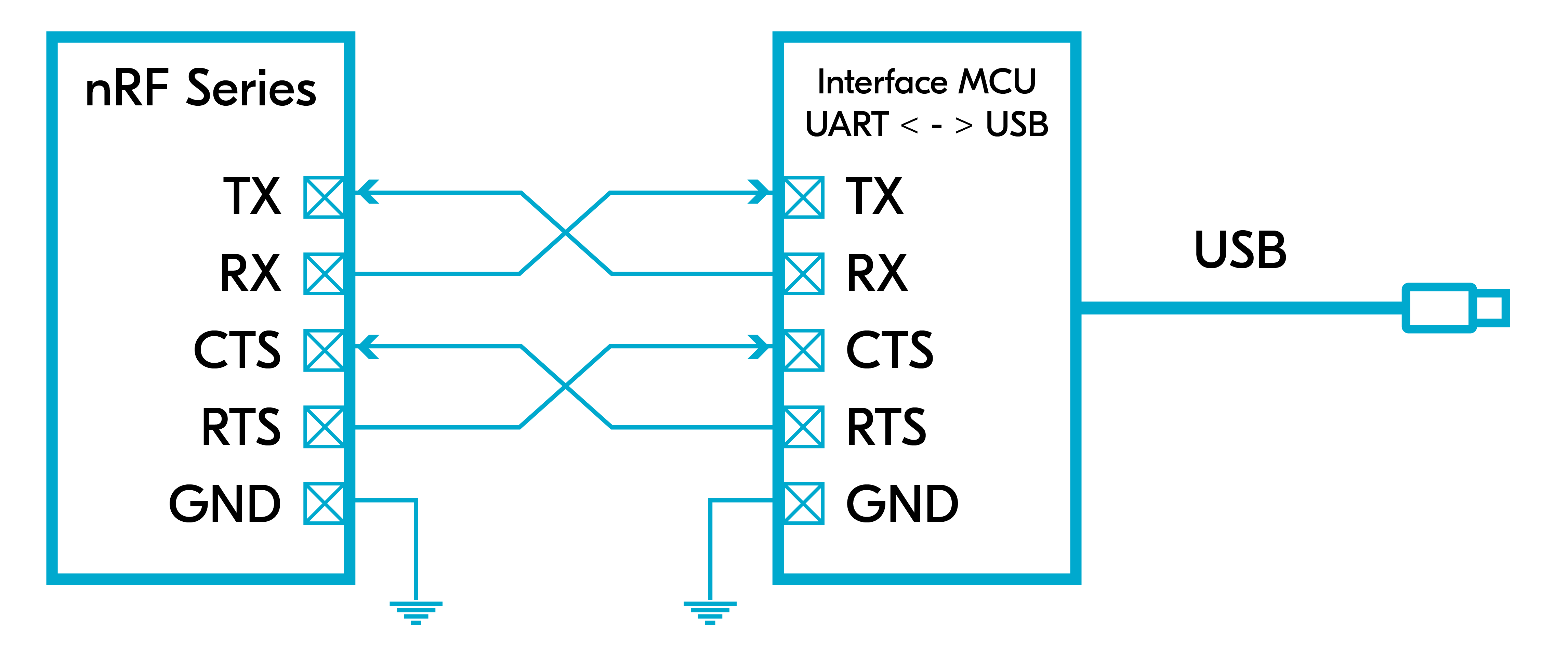
We will set up the UART in asynchronous mode so that a callback function is called every time there is new data. We will set up the receive buffer size to 10 bytes and the receive timeout to 100 microseconds. This means when a byte is received and there is inactivity (no new data) after 100 microseconds, or 10 bytes is received, a UART_RX_RDY event is generated.
In this exercise, we will simply practice the steps covered in the UART Driver section to interact with the UART hardware in an asynchronous manner.
Note
This exercise is not supported on the Thingy (Thingy:53, Thingy:91, Thingy:91 X).
Exercise steps
1. In the GitHub repository for this course, open the base code for this exercise, found in l5/l5_e1 of whichever version directory you are using.
This code is based on the blinky sample.
2. Enable the serial driver (UART driver) by adding the following two lines in prj.conf.
CONFIG_SERIAL=y
CONFIG_UART_ASYNC_API=yAs we mentioned before, the first line is usually enabled by default through the board’s devicetree, and you should therefore see it in gray (only when a build configuration has been added to the project). However, the second line is important to enable the asynchronous API of the serial driver.
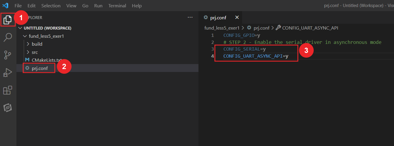
Hover your mouse over the Kconfig symbol that is greyed out, to see the configuration conflict, see the image below.

3. Include the header file of the UART driver in main.c.
#include <zephyr/drivers/uart.h>4. Get the device pointer of the UART hardware and verify that it is ready.
4.1 Get the device pointer of the UART hardware.
Remember, in nRF Connect SDK, any peripheral is accessed as a pointer of type struct device.
const struct device *uart= DEVICE_DT_GET(DT_NODELABEL(uart0));4.2 Verify that the UART device is ready.
	if (!device_is_ready(uart)){
		printk("UART device not ready\r\n");
		return 1 ;
}5. Get the device pointers of the LEDs through gpio_dt_spec and verify that it is ready.
5.1 Get the device pointer of the LEDs
Since we are using UART to control the LEDs (1-3) on the development kit, we need to get the device pointer for these as well. As we saw in Lesson 2, this is encapsulated in the API-specific structure gpio_dt_spec and can be retrieved using GPIO_DT_SPEC_GET().
Keep in mind that the nRF7002DK has only 2 LEDs. Therefore, we must include a compile-time if-condition which automatically checks the DK you are building for. If it finds you are building for the nRF7002DK, it will run a slightly different code for this step, excluding the 3rd LED (LED2), to mitigate this issue.
#if defined (CONFIG_BOARD_NRF7002DK_NRF5340_CPUAPP)|| defined (CONFIG_BOARD_NRF7002DK_NRF5340_CPUAPP_NS)
static const struct gpio_dt_spec led0 = GPIO_DT_SPEC_GET(DT_ALIAS(led0), gpios);
static const struct gpio_dt_spec led1 = GPIO_DT_SPEC_GET(DT_ALIAS(led1), gpios);
#else
static const struct gpio_dt_spec led0 = GPIO_DT_SPEC_GET(DT_ALIAS(led0), gpios);
static const struct gpio_dt_spec led1 = GPIO_DT_SPEC_GET(DT_ALIAS(led1), gpios);
static const struct gpio_dt_spec led2 = GPIO_DT_SPEC_GET(DT_ALIAS(led2), gpios);
#endif
5.2 Verify that the LED devices are ready.
Since all the LEDs are associated with the same port, &gpio0, we only need to check one of the devices.
	if (!device_is_ready(led0.port)){
		printk("GPIO device is not ready\r\n");
		return 1;
}6. Configure the GPIOs of the LEDs
As previously explained in step 5.1, there will be a compile-time if-condition added to make sure the code builds when using the nRF7002DK.
#if defined (CONFIG_BOARD_NRF7002DK_NRF5340_CPUAPP)|| defined (CONFIG_BOARD_NRF7002DK_NRF5340_CPUAPP_NS)
	ret = gpio_pin_configure_dt(&led0, GPIO_OUTPUT_ACTIVE);
	if (ret < 0) {
		return 1 ;
	}
	ret = gpio_pin_configure_dt(&led1, GPIO_OUTPUT_ACTIVE);
	if (ret < 0) {
		return 1 ;
	}
#else
ret = gpio_pin_configure_dt(&led0, GPIO_OUTPUT_ACTIVE);
	if (ret < 0) {
		return 1 ;
	}
	ret = gpio_pin_configure_dt(&led1, GPIO_OUTPUT_ACTIVE);
	if (ret < 0) {
		return 1 ;
	}
	ret = gpio_pin_configure_dt(&led2, GPIO_OUTPUT_ACTIVE);
	if (ret < 0) {
		return 1 ;
	}
#endif7. Define the application callback function for UART. For our simple LED application, we are only interested in the UART_RX_RDY and the UART_RX_DISABLED events related to receiving data over UART. For your own application, this might differ as we discussed in the UART driver section.
As previously explained in step 5.1, there will be a compile-time if-condition added to make sure the code builds when using the nRF7002DK.
static void uart_cb(const struct device *dev, struct uart_event *evt, void *user_data)
{
	switch (evt->type) {

	case UART_RX_RDY:
#if defined(CONFIG_BOARD_NRF7002DK_NRF5340_CPUAPP) ||                                              \
	defined(CONFIG_BOARD_NRF7002DK_NRF5340_CPUAPP_NS)
		if ((evt->data.rx.len) == 1) {

			if (evt->data.rx.buf[evt->data.rx.offset] == '1') {
				gpio_pin_toggle_dt(&led0);
			} else if (evt->data.rx.buf[evt->data.rx.offset] == '2') {
				gpio_pin_toggle_dt(&led1);
			}
		}
#else
		if ((evt->data.rx.len) == 1) {

			if (evt->data.rx.buf[evt->data.rx.offset] == '1') {
				gpio_pin_toggle_dt(&led0);
			} else if (evt->data.rx.buf[evt->data.rx.offset] == '2') {
				gpio_pin_toggle_dt(&led1);
			} else if (evt->data.rx.buf[evt->data.rx.offset] == '3') {
				gpio_pin_toggle_dt(&led2);
			}
		}
#endif
		break;
	case UART_RX_DISABLED:
		uart_rx_enable(dev, rx_buf, sizeof rx_buf, RECEIVE_TIMEOUT);
		break;

	default:
		break;
	}
}Note
With if((evt->data.rx.len) == 1), we are assuming a terminal in char mode, which is the default terminal in nRF Connect for VS Code (nRF Terminal) and PuTTY. These two terminal by default, does not require you to press enter to send the date, hence do not send extra bytes.
On the other hand, if you are using a serial terminal in “line mode”, you need to press enter to send the data, which typically sends two extra bytes “/r/n” (Depending on the terminal configuration). Therefore you need to change the condition to match the length of the data you are sending.
8. Register the UART callback function by calling the function uart_callback_set().
	ret = uart_callback_set(uart, uart_cb, NULL);
		if (ret) {
			return 1;
}9. Now let’s send some data over UART.
9.1 Define the transmission buffer, which is a buffer to hold the data to be sent over UART.
static uint8_t tx_buf[] =   {"nRF Connect SDK Fundamentals Course\r\n"
"Press 1-3 on your keyboard to toggle LEDS 1-3 on your development kit\r\n"};9.2 Send the data over UART by calling uart_tx(). Since we are not using flow control, pass SYS_FOREVER_US to disable transmission timeout. This is not related to receiving timeout.
	ret = uart_tx(uart, tx_buf, sizeof(tx_buf), SYS_FOREVER_US);
	if (ret) {
		return 1;
}10. Let’s start receiving data!
10.1 Define the receive buffer. For this simple exercise of controlling LEDs through UART, we will define a small buffer of size 10 of type uint8_t.
10.1.1 Define the size of the receive buffer.
#define RECEIVE_BUFF_SIZE 1010.1.2 Define the receive buffer and initialize its members to zeros.
static uint8_t rx_buf[RECEIVE_BUFF_SIZE] = {0};10.2 Define the receiving timeout period to be 100 microseconds. This means when a byte is received and there is inactivity (no new data) for 100 microseconds, a UART_RX_RDY event is generated. If you are going to use receive timeout in your application, pick a value that matches your application requirements.
#define RECEIVE_TIMEOUT 10010.3 Start receiving by calling uart_rx_enable() and pass it the address of the receive buffer.
	ret = uart_rx_enable(uart ,rx_buf,sizeof rx_buf,RECEIVE_TIMEOUT);
	if (ret) {
		return 1;
}11. Build the application and flash it on your development kit.
Testing
12. You should observe that the three LEDs on your development kit are all switched on. Using a serial terminal such as the integrated nRF Terminal or PuTTY, you should see the below output:
*** Booting nRF Connect SDK 2.6.1-3758bcbfa5cd ***
nRF Connect SDK Fundamentals Course
Press 1-3 on your keyboard to toggle LED 1-3 on your development kitWe are using the default baud rate (115200) and UART settings set in the devicetree. If you want to change that, you can do it using the UART API as explained earlier.
Writing a number from 1 to 3 in the serial emulator will toggle the corresponding LED on your development kit.
Note
If you are using a Thingy:91, LED1 is the red LED, LED2 is the green LED and LED3 is the blue LED.
The solution for this exercise can be found in the GitHub repository, l5/l5_e1_sol of whichever version directory you are using.

