

演習1:Matterデバイスの実行と制御
この演習では、nRF Connect SDKのMatterドアロックサンプルを実行し、CHIP Toolを使用して開発者向けMatterコントローラでテストします。
注意
この演習では、Matterロックサンプルの基本的な使用方法のみを紹介します。本サンプルのさまざまな構成について詳しく学びたい場合は、ドキュメントページをご覧ください。
レッスン1で、MatterコントローラはMatterインフラストラクチャ内のデバイスであり、エンドユーザーがMatterアクセサリを制御するために使用することを学びました。実用上の理由から、市販でMatterコントローラとして機能できるデバイスは通常、スマートフォンまたはスマートハブです。しかし、これらのデバイスは公式にリリースされ認証済みのMatterソフトウェアを使用している一方で、開発者は市販デバイスではテストできない新機能を開発したいことがよくあります。また、PCで利用できるツールを使って作業する方が、開発者にとってはるかに便利です。
この目的のためにCHIP Toolを使用します。CHIP ToolはMatterコントローラの役割のデフォルト実装であり、Matter開発者が、市販製品としてリリースする前にアプリケーションをテストするために広く使用しています。また、nRF Connect SDKプラットフォームでの開発にも推奨されます。
重要
Windows/macOSユーザー:この演習および以降のすべての演習では、CHIP Toolを実行するためにRaspberry Piが必要です。
開始するには、Raspberry Piのセットアップと接続方法をご覧ください。
Matterコントローラを実行するPCがThreadプロトコルをサポートしていないため、CHIP Toolを使用してMatter over Threadデバイスと直接通信することはできません。そのため、デバイス間の通信を変換する追加のThread Border Routerデバイスが必要です。
MatterコントローラおよびThread Border RouterのホストアプリケーションはPC上で実行できますが、PCにはThreadプロトコルで通信するための無線トランシーバが内蔵されていません。このため、Threadデバイスと通信するには、USB接続の外部無線コプロセッサ(RCP)デバイスが必要です。この演習では、その目的のために2台目のNordic DKを使用します。
次の画像は、説明したセットアップを示しています。

Matterコントローラを実行するPCがWi-Fiプロトコルをサポートしているため、CHIP Toolを使用してMatter over Wi-Fiデバイスと直接通信できます。
次の画像は、説明したセットアップを示しています。

演習手順
1. Matterドアロックサンプルの実行
1.1 Visual Studio CodeのWELCOMEパネルで「Browse samples」を選択し、SDKバージョンを選択してから「Matter Lock」を検索します。

サンプルを選択すると、APPLICATIONSパネルに表示されます。
1.2 ビルド構成を追加します

1.3 使用しているDKに対応するボードターゲットを選択します
| nRF54L15 DK | nrf54l15dk/nrf54l15/cpuapp |
| nRF54LM20 DK | nrf54lm20dk/nrf54lm20a/cpuapp |
下部のGenerate and Buildボタンをクリックしてサンプルをビルドします

ビルドプロセスが終了すると、ビルドディレクトリがAPPLICATIONSパネルに表示されます。

1.4 USB-CケーブルでnRF54L Series DKをPCに接続します。POWERスイッチがONになっていることを確認してください。すると、CONNECTED DEVICESパネルにデバイスが表示されます。

1.5 ACTIONSパネルのFlashボタンを使用してアプリケーションをボードに書き込みます。右側のErase and Flash to Boardアイコンを使用してください。

書き込みが完了したら、ボード上のLEDを確認します。ボードのLED0が点滅し、アプリケーションは実行中ですがデバイスがネットワークに接続されていないことを示します。LED1はロックの状態を表し、点灯しているはずです。これはロックが閉じていることを意味します。
注意
nRF54LM20 DKのリビジョン<0.5.0を使用している場合は、nRF Connect for DesktopのBoard ConfiguratorアプリケーションでVDD_NRFとVDDIOを2.7 V未満に設定する必要があります。VDD_NRFおよびVDDIOの値を2.7 Vより大きく設定すると、DK上のLEDが動作しなくなります。

1.6 CONNECTED DEVICESパネルのVCOMを使用して、ボードのシリアルポートを開きます。VCOMの右側にあるConnect to Serial Portアイコンをクリックします。
デバイスからのログが表示されない場合は、nRF54L Series DKのRESETボタンをクリックしてください。
注意
nRF54L Series DKは2つのシリアルポートとして認識され、番号はPCによって異なる場合があります。番号が大きい方のVCOMを選択してください。例えばVCOM0とVCOM1がある場合はVCOM1を使用します。

Terminalウィンドウに、次のようなログが表示されるはずです。

Matterドアロックデバイスは以降の操作に使用できる状態ですが、ネットワークに接続する前に、残りのデバイスをセットアップする必要があります。
2. Thread Border Routerのセットアップ
開発目的であれば、アプリケーションを手動でビルドすることなく、Linuxベースの任意のシステム上でDockerコンテナとしてOpenThread Border Routerを実行できます。
PCからThreadデバイスへ接続する手段を提供するために、OpenThread Border RouterにはThread無線コプロセッサが必要です。これはNordic Development KitとThread Coprocessorサンプルを使用して作成できます。 (nRF Connect SDKより)
2.1 Visual Studio CodeのWELCOMEパネルで「Browse samples」を選択し、「OpenThread Coprocessor」を検索します。

注意
OpenThread Co-Processorサンプルは2つ見つかります。1つはnrfディレクトリに、もう1つはzephyrディレクトリにあります。nrfにあるサンプルはNordicがメンテナンスしており、使用が推奨されます。一方、zephyrのサンプルの品質はNordicによって検証されていません。
nrfのOpenThread Co-processorサンプルを選択すると、APPLICATIONSパネルに表示されます。
2.2 ビルド構成を追加します

2.3 使用しているDKに対応するボードターゲットを選択します(
| nRF54L15 DK | nrf54l15dk/nrf54l15/cpuapp |
| nRF54LM20 DK | nrf54lm20dk/nrf54lm20a/cpuapp |
| nRF52840 dongle | nrf52840dongle/nrf52840 |
| nRF52840 DK | nrf52840dk/nrf52840 |
| nRF52833 DK | nrf52833dk/nrf52833 |
下部のGenerate and Buildボタンをクリックしてサンプルをビルドします。

ビルドプロセスが終了すると、ビルドディレクトリがAPPLICATIONSパネルに表示されます。
2.4 DKをPCに接続します。POWERスイッチがONになっていることを確認してください。ドングルの場合は、コンピュータのUSBポートに直接挿してください。
デバイスがCONNECTED DEVICESパネルに表示されます。
切り替え可能なタブ:DK
2.5 ACTIONSパネルのFlashボタンを使用してアプリケーションをボードに書き込みます。右側のErase and Flash to Boardアイコンを使用してください。
切り替え可能なタブ:dongle
2.5 ドングルにアプリケーションを書き込みます。
nRF52840 Dongleは、開発キットとは異なりオンボードデバッガを搭載していません。そのため、ファームウェアの書き込み手順が異なります。
2.5.1 RESETボタンを押してドングルをDFUモードにします。ボタンはUSBコネクタから見て基板の反対側にあり、上向きではありません。外側から内側へ、USBコネクタの方向に押し込む必要があります。
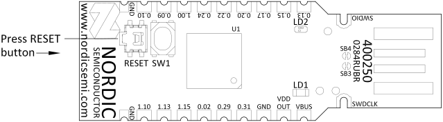
RGBライトがフェードしながら赤色に点灯し、ドングルがDFUモードであることを示します。
2.5.2 ターミナルで次のコマンドを入力し、Nordicのブートローダと互換性のあるファームウェアパッケージを生成します。
Radio Coprocessorサンプルの/build/coprocessor/zephyrディレクトリ(<ncs_install_path>/nrf/samples/openthread/coprocessor))に移動し、次のコマンドをターミナルで順に実行します。
nrfutil install nrf5sdk-tools
nrfutil pkg generate --hw-version 52 --sd-req=0x00 --application zephyr.hex --application-version 1 app.zip
2.5.3 次のコマンドを実行して、ファームウェアパッケージをnRF52840 Dongleに書き込みます。
nrfutil device program --firmware app.zip --traits nordicDfu
2.6 次の手順で必要になるため、CONNECTED DEVICES パネルでThread Coprocessorサンプルが使用しているVCOM番号を控えてください。この例では/dev/ttyACM0ですが、PCによって異なる場合があります。
注意
nRF54L Series DKは2つのシリアルポートとして認識され、番号はPCによって異なる場合があります。番号が大きい方のVCOMを選択してください。例えばVCOM0とVCOM1がある場合はVCOM1を使用します。

これでThread無線コプロセッサデバイスの準備ができたので、OpenThread Border Routerアプリケーションの実行に進めます。
以降の手順は、ツール要件がWindowsやmacOSでサポートされていないため、Raspberry PiまたはUbuntu 24.04 LTS上で実行する必要があります。
2.7 コマンドラインターミナルを開きます。
2.8 次のコマンドを実行してDockerデーモンをインストールします。
sudo apt update && sudo apt install docker.io2.9 次のコマンドを実行してDockerデーモンを起動します。
sudo systemctl start docker2.10 次のコマンドを実行して、互換性のあるバージョンのOpenThread Border RouterのDockerイメージをダウンロードします。
sudo docker pull nrfconnect/otbr:fbde28a2.11 DockerでOpenThread Border Routerコンテナ用のIPv6ネットワークを作成します。
sudo docker network create --ipv6 --subnet fd11:db8:1::/64 -o com.docker.network.bridge.name=otbr0 otbr2.12 IPv6テーブルフィルタを設定します
sudo modprobe ip6table_filter2.13 OpenThread Border Routerを起動します。
次のコマンド内の/dev/ttyACM0は、手順2.6で控えたThread Coprocessorデバイスのシリアルポート番号に置き換える必要があります。
ターミナルで次のコマンドを実行してOpenThread Border Routerを起動します。
sudo docker run -it --rm --privileged --name otbr --network otbr -p 8080:80 \ --sysctl "net.ipv6.conf.all.disable_ipv6=0 net.ipv4.conf.all.forwarding=1 net.ipv6.conf.all.forwarding=1" \ --volume /dev/ttyACM0:/dev/radio nrfconnect/otbr:fbde28a --radio-url spinel+hdlc+uart:///dev/radio?uart-baudrate=10000002.14 Webブラウザでhttp://localhost:8080/アドレスを開き、OpenThread Border RouterのGUIにアクセスします。
2.15 サイドパネルからFormタブに移動します。ネットワークパラメータは自動的に入力されており、変更する必要はありません。

注意
複数の分離されたThreadネットワークを実行したい場合、デフォルトのThreadネットワークパラメータを変更すると便利です。ネットワーク間の競合を避けるため、各ネットワークのパラメータを変更する必要があります。
Threadネットワークパラメータの目的は次のとおりです。
- Network Name:Threadネットワークの人間が読める名称です。
- Network Extended PAN ID:ネットワークを識別するための一意のネットワークIDです。
- PAN ID:MACレイヤーでフレームをフィルタリングするために使用されるパーソナルエリアネットワークIDです。
- Passphrase:Threadコミッショニング用の人間が読めるパスフレーズで、Matterプロトコルの文脈では使用されません。
- Network Key:ネットワーク内のすべてのノードで共有されるキーで、Threadトラフィックを暗号化するためのセキュリティキーを導出するために使用されます。
- Channel:ネットワークで使用されるIEEE 802.15.4の無線チャネル番号です。
- On-Mesh Prefix:ネットワーク内で広告されるIPv6プレフィックスで、ルーティング目的で使用されます。
- Default Router:Thread Border Routerがメッシュにデフォルトルートを広告し、ノードがルータ経由でオフメッシュトラフィックを送信できるようにするチェックボックスです。
2.16 FORM ボタンを押して、OpenThread Border RouterにThreadネットワークの形成を要求し、Threadリーダーになります。表示される「Are you sure?」ポップアップではOkayを押してください。
nRF54L Series DKでFORM操作が失敗した場合は、手順2.13のコマンドを、DKのもう一方のVCOMポートで再実行してみてください。
それでもエラーメッセージが表示される場合は、次をお試しください。
- USBケーブルを抜き差しする。
- OpenThread Coprocessorファームウェアを再度書き込む(手順2.5.2)。
- Raspberry PiまたはUbuntuシステムを再起動する。Dockerイメージが正しく動作していない場合があり、再起動によりDockerの状態が更新されることがあります。
2.18 新しいターミナルを開き、次のコマンドを実行して、Threadネットワーク内のデバイス宛てパケットがDocker内のOpenThread Border Routerコンテナを経由してルーティングされることを確認します。
sudo ip -6 route add fd11:22::/64 dev otbr0 via fd11:db8:1::22.19 Docker内で動作しているThreadノードの状態を確認します。
sudo docker exec -it otbr sh -c "sudo ot-ctl state"出力は次のようになるはずです。
leader
DoneThread Border Routerデバイスは、以降の操作に使用できる状態です。
ただし、Matter over Threadデバイスをネットワークに接続する前に、Matterコントローラをセットアップする必要があります。
3. CHIP Tool Matterコントローラのセットアップ
3.1 Matter nRF Connect releasesのGitHubページに移動し、CHIP Toolの実行ファイルをダウンロードします。使用しているnRF Connect SDKリリースと互換性のあるリリースアーティファクトを見つけてください。

3.2 CHIP Toolの実行ファイルをクリックしてダウンロードします。
- LinuxのPCでセットアップを行うユーザーは、chip-tool_x64ファイルをダウンロードしてください。
- Raspberry Piでセットアップを行うユーザーは、chip-tool_arm64ファイルをダウンロードしてください。
3.3 次のコマンドを使用して、ダウンロードしたバイナリファイルを実行します。
PCの場合:
./chip-tool_x64 interactive start
Raspberry Piの場合:
./chip-tool_arm64 interactive start
アプリケーションは次のようなログを出力するはずです。
[1769459696.750] [32122:32122] [DL] ChipLinuxStorage::Init: Using KVS config file: /tmp/chip_tool_kvs
[1769459696.750] [32122:32122] [DL] ChipLinuxStorage::Init: Attempt to re-initialize with KVS config file: /tmp/chip_kvs, IGNORING.
[1769459696.751] [32122:32122] [DL] ChipLinuxStorage::Init: Using KVS config file: /tmp/chip_factory.ini
[1769459696.751] [32122:32122] [DL] ChipLinuxStorage::Init: Using KVS config file: /tmp/chip_config.ini
[1769459696.751] [32122:32122] [DL] ChipLinuxStorage::Init: Using KVS config file: /tmp/chip_counters.ini
[1769459696.760] [32122:32122] [DL] Wrote settings to /tmp/chip_counters.ini
[1769459696.760] [32122:32122] [DL] NVS set: chip-counters/reboot-count = 2 (0x2)
[1769459696.760] [32122:32122] [DL] Got Ethernet interface: enp0s31f6
[1769459696.760] [32122:32122] [DL] Found the primary Ethernet interface:enp0s31f6
[1769459696.761] [32122:32122] [DL] Got WiFi interface: wlp0s20f3
[1769459696.761] [32122:32122] [DL] Failed to reset WiFi statistic counts
[1769459696.761] [32122:32122] [PAF] WiFiPAF: WiFiPAFLayer::Init()
[1769459696.761] [32122:32122] [IN] UDP::Init bind&listen port=0
[1769459696.761] [32122:32122] [IN] UDP::Init bound to port=48497
[1769459696.761] [32122:32122] [IN] UDP::Init bind&listen port=0
[1769459696.761] [32122:32122] [IN] UDP::Init bound to port=59045
[1769459696.761] [32122:32122] [IN] BLEBase::Init - setting/overriding transport
[1769459696.761] [32122:32122] [IN] WiFiPAFBase::Init - setting/overriding transport
[1769459696.761] [32122:32122] [IN] TransportMgr initialized
[1769459696.761] [32122:32122] [FP] Initializing FabricTable from persistent storage
[1769459696.761] [32122:32122] [TS] Last Known Good Time: 2023-10-14T01:16:48
[1769459696.762] [32122:32122] [DMG] Ember attribute persistence requires setting up
[1769459696.762] [32122:32122] [ZCL] Using ZAP configuration...
[1769459696.765] [32122:32122] [DL] Avahi client registered
[1769459696.765] [32122:32122] [IN] CASE Server enabling CASE session setups
[1769459696.765] [32122:32122] [IN] SecureSession[0x5ac1e6ce54c0]: Allocated Type:2 LSID:52055
[1769459696.765] [32122:32122] [SC] Allocated SecureSession (0x5ac1e6ce54c0) - waiting for Sigma1 msg
[1769459696.765] [32122:32122] [CTL] System State Initialized...
[1769459696.765] [32122:32122] [CTL] Setting attestation nonce to random value
[1769459696.765] [32122:32122] [CTL] Setting CSR nonce to random value
[1769459696.766] [32122:32124] [DL] CHIP task running
[1769459696.766] [32122:32124] [DL] HandlePlatformSpecificBLEEvent 32786これでMatterコントローラデバイスの準備ができたので、Matterドアロックデバイスのコミッショニングに進めます。
4. Matterデバイスのコミッショニングと制御
4.1 新しいコマンドラインターミナルを開きます。
4.2 次のコマンドを使用してThreadネットワークのデータセットを取得します。
sudo docker exec -it otbr sh -c "ot-ctl dataset active -x"出力は次のようになります。
080000000000000000000300001735060004001fffe00208deadbeefcafe12340708fd123456789abc00000510112233445566778899aabbccddeeff00030a54657374576f726b3031010211220410aabbccddeeff00112233445566778899aa0c0402a0f7f8 Done注意
例に示されているデータセットは、お使いのデバイスに表示されるものとは異なります。以降の手順では必ずご自身のデータセットを使用してください。
以降の演習でコマンドを再実行せずに使えるよう、データセットをPC上のどこかに保存しておいてください。
4.3 MatterドアロックボードのButton 0を押して、Bluetooth LE経由のMatterアドバタイズを開始します。4.4
デバイスのシリアルポートに次のログが表示されるはずです。
I: 730208 [DL]CHIPoBLE advertising started
I: 730212 [DL]NFC Tag emulation started注意
「CHIPoBLE」という名称は、MatterプロトコルがConnected Home over IP(CHIP)と呼ばれていた頃のレガシー用語です。Matterスタック内では更新されていません。
4.4 手順3.3でCHIP Toolアプリケーションを実行しているターミナルウィンドウに戻ります。
次のコマンドを実行してコミッショニングプロセスを開始し、引数<thread dataset>に手順4.2で取得したThreadデータセットを入力します。
pairing ble-thread <your_selected_node_id> hex:<thread dataset> 20202021 3840<your_selected_node_id>を、この演習でのみ使用するランダムなノードID(例:1)に置き換えてください。この同じ番号は、CHIP Toolを介してデバイスにコマンドを送信する際にも使用します。
次のコマンド内の20202021と3840は、それぞれペアリングPINコードとデバイスのペアリングディスクリミネータです。専用のKconfigオプションCONFIG_CHIP_DEVICE_SPAKE2_PASSCODEおよびCONFIG_CHIP_DEVICE_DISCRIMINATORを使用して別の値に設定できます。
この演習ではデフォルト値を使用します。
その結果、MatterドアロックデバイスとCHIP Toolアプリケーションは、コミッショニングフローを示す多数の詳細ログメッセージを出力し始めます。これらは、ペアリングに問題がある場合に特に有用で、トラブルシューティングに役立ちます。
MatterドアロックデバイスのLED0が高速点滅しているはずです。これはコミッショニング処理の途中であることを意味します。コミッショニングが成功すると、LED0は点灯します。
コミッショニングが成功すると、CHIP Toolのターミナルに次のログが表示されるはずです。
[1769669998.755] [13455:13457] [CTL] Commissioning complete for node ID 0x0000000000000001: success
[1769669998.755] [13455:13457] [TOO] Device commissioning completed with successMatterドアロックのターミナルには次のログが表示されます。
I: 40994 [SVR]Commissioning completed successfully
I: 40999 [DIS]Updating services using commissioning mode 0
I: 41004 [DIS]Advertise operational node C0A6EA990FC57325-0000000000000001
I: 41010 [SC]SecureSession[0x2000f648, LSID:33768]: State change 'kActive' --> 'kPendingEviction'
I: 41019 [BLE]Releasing end point's BLE connection back to application.
I: 41025 [DL]Closing BLE GATT connection (ConnId 00)
I: 41114 [DL]Current number of connections: 0/1
I: 41118 [DL]BLE GAP connection terminated (reason 0x16)4.5 CHIP Toolのターミナルウィンドウで次のコマンドを実行し、MatterコントローラからMatterロックのロック解除を行います。
<your_selected_node_id>を、手順4.4でデバイスをペアリングした際に使用したノードIDに置き換えてください。
doorlock unlock-door <your_selected_node_id> 1 --timedInteractionTimeoutMs 5000MatterドアロックデバイスのLED1がしばらく点滅し、最終的に消灯することを確認してください。これはロックが開いていることを意味し、点滅は物理的なデッドボルトが開くまでに必要な時間をエミュレートしています。
4.6 CHIP Toolのターミナルウィンドウで次のコマンドを実行し、MatterコントローラからMatterロックを施錠します。
doorlock lock-door <your_selected_node_id> 1 --timedInteractionTimeoutMs 5000MatterドアロックデバイスのLED1がしばらく点滅し、最終的に点灯することを確認してください。これはロックが閉じていることを意味し、点滅は物理的なデッドボルトが閉まるまでにかかる時間をエミュレートしています。
1. Matterドアロックサンプルの実行
1.1 Visual Studio CodeのWELCOMEパネルで「Browse samples」を選択し、SDKバージョンを選択してから「Matter Lock」を検索します。

このサンプルを選択すると、APPLICATIONSパネルに表示されます。
1.2 ビルド構成を追加します

1.3 nrf54lm20dk/nrf54lm20/cpuappをボードターゲットとして選択します。次に、nRF7002 EB IIシールドとWi-Fiプロトコルをサポートするため、Extra CMake argumentsセクションに次の引数を追加します。
- -DSHIELD=nrf7002eb2
- -DSB_CONFIG_WIFI_NRF70=y
- -DCONFIG_CHIP_WIFI=y
その後、Generate and Buildボタンをクリックしてこのサンプルをビルドします。

ビルドプロセスが終了すると、ビルドディレクトリがAPPLICATIONSパネルに表示されます。

1.4 USB-Cケーブルで、DEBUGGER USBポートを使用してnRF54LM20 DKボードをPCに接続します。POWERスイッチがONになっていることを確認してください。
デバイスがCONNECTED DEVICES パネルに表示されるはずです。

1.5 ACTIONSパネルのFlashボタンを使用してアプリケーションをボードに書き込みます。右側のErase and Flash to Boardアイコンを使用してください。

書き込みが完了したら、ボード上のLEDを確認します。ボードのLED0が点滅している場合、アプリケーションは実行中ですがデバイスがネットワークに接続されていないことを意味します。LED1はロックの状態を示し、点灯しているはずです。これはロックが閉じていることを意味します。
1.6 CONNECTED DEVICESパネルのVCOMを使用して、ボードのシリアルポートを開きます。デバイスからのログが表示されない場合は、nRF54LM20 DKのRESETボタンをクリックしてください。
注意
nRF54LM20 DKは2つのシリアルポートとして認識され、番号はPCによって異なる場合があります。番号が大きい方のVCOMを選択してください。例えばVCOM0とVCOM1がある場合はVCOM1を使用します。

Terminalウィンドウに、次のようなログが表示されるはずです。

Matterドアロックデバイスは以降の操作に使用できる状態ですが、ネットワークに接続する前に、残りのデバイスをセットアップする必要があります。
2. CHIP Tool Matterコントローラのセットアップ
2.1 Matter nRF Connect releasesのGitHubページに移動し、CHIP Toolの実行ファイルをダウンロードします。使用しているnRF Connect SDKリリースと互換性のあるリリースアーティファクトを見つけてください。

2.2 CHIP Toolの実行ファイルをクリックしてダウンロードします。
- Ubuntu 24.04 LTSでセットアップを行うユーザーは、chip-tool_x64ファイルをダウンロードしてください。
- Raspberry Piでセットアップを行うユーザーは、chip-tool_arm64ファイルをダウンロードしてください。
2.3 次のコマンドを使用して、ダウンロードしたバイナリファイルを実行します。
PCの場合:
./chip-tool_x64 interactive start
Raspberry Piの場合:
./chip-tool_arm64 interactive start
その結果、アプリケーションは次のようなログを出力するはずです。
[1769459696.750] [32122:32122] [DL] ChipLinuxStorage::Init: Using KVS config file: /tmp/chip_tool_kvs
[1769459696.750] [32122:32122] [DL] ChipLinuxStorage::Init: Attempt to re-initialize with KVS config file: /tmp/chip_kvs, IGNORING.
[1769459696.751] [32122:32122] [DL] ChipLinuxStorage::Init: Using KVS config file: /tmp/chip_factory.ini
[1769459696.751] [32122:32122] [DL] ChipLinuxStorage::Init: Using KVS config file: /tmp/chip_config.ini
[1769459696.751] [32122:32122] [DL] ChipLinuxStorage::Init: Using KVS config file: /tmp/chip_counters.ini
[1769459696.760] [32122:32122] [DL] Wrote settings to /tmp/chip_counters.ini
[1769459696.760] [32122:32122] [DL] NVS set: chip-counters/reboot-count = 2 (0x2)
[1769459696.760] [32122:32122] [DL] Got Ethernet interface: enp0s31f6
[1769459696.760] [32122:32122] [DL] Found the primary Ethernet interface:enp0s31f6
[1769459696.761] [32122:32122] [DL] Got WiFi interface: wlp0s20f3
[1769459696.761] [32122:32122] [DL] Failed to reset WiFi statistic counts
[1769459696.761] [32122:32122] [PAF] WiFiPAF: WiFiPAFLayer::Init()
[1769459696.761] [32122:32122] [IN] UDP::Init bind&listen port=0
[1769459696.761] [32122:32122] [IN] UDP::Init bound to port=48497
[1769459696.761] [32122:32122] [IN] UDP::Init bind&listen port=0
[1769459696.761] [32122:32122] [IN] UDP::Init bound to port=59045
[1769459696.761] [32122:32122] [IN] BLEBase::Init - setting/overriding transport
[1769459696.761] [32122:32122] [IN] WiFiPAFBase::Init - setting/overriding transport
[1769459696.761] [32122:32122] [IN] TransportMgr initialized
[1769459696.761] [32122:32122] [FP] Initializing FabricTable from persistent storage
[1769459696.761] [32122:32122] [TS] Last Known Good Time: 2023-10-14T01:16:48
[1769459696.762] [32122:32122] [DMG] Ember attribute persistence requires setting up
[1769459696.762] [32122:32122] [ZCL] Using ZAP configuration...
[1769459696.765] [32122:32122] [DL] Avahi client registered
[1769459696.765] [32122:32122] [IN] CASE Server enabling CASE session setups
[1769459696.765] [32122:32122] [IN] SecureSession[0x5ac1e6ce54c0]: Allocated Type:2 LSID:52055
[1769459696.765] [32122:32122] [SC] Allocated SecureSession (0x5ac1e6ce54c0) - waiting for Sigma1 msg
[1769459696.765] [32122:32122] [CTL] System State Initialized...
[1769459696.765] [32122:32122] [CTL] Setting attestation nonce to random value
[1769459696.765] [32122:32122] [CTL] Setting CSR nonce to random value
[1769459696.766] [32122:32124] [DL] CHIP task running
[1769459696.766] [32122:32124] [DL] HandlePlatformSpecificBLEEvent 32786これでMatterコントローラデバイスの準備ができたので、Matterドアロックデバイスのコミッショニングに進めます。
3. Matterデバイスのコミッショニングと制御
3.1 コマンドラインターミナルを開きます。
3.2 CHIP Toolを実行しているマシンが現在使用しているWi-FiネットワークのSSIDとパスワードを取得します。
3.3 MatterドアロックボードのButton 0を押して、Bluetooth LE経由のMatterアドバタイズを開始します。
デバイスのシリアルポートに次のログが表示されるはずです。
I: 730208 [DL]CHIPoBLE advertising started
I: 730212 [DL]NFC Tag emulation started注意
「CHIPoBLE」という名称は、MatterプロトコルがConnected Home over IP(CHIP)と呼ばれていた頃のレガシー用語です。Matterスタック内では更新されていません。
3.4 CHIPToolアプリケーションを実行しているターミナルウィンドウを使用してコミッショニングプロセスを開始します。次のコマンドを実行し、<wifi_ssid>および<wifi_password>引数に、手順3.2で取得したWi-Fiネットワーク情報を入力します。
pairing ble-wifi <your_selected_node_id> <wifi_ssid> <wifi_password> 20202021 3840<your_selected_node_id>を、この演習でのみ使用するランダムなノードID(例:1)に置き換えてください。この同じ番号は、CHIP Toolを介してデバイスにコマンドを送信する際にも使用します。
次のコマンド内の20202021と3840は、それぞれペアリングPINコードとデバイスのディスクリミネータです。専用のKconfigオプションを使用して別の値に設定できますが、この演習ではデフォルト値を使用します。
その結果、MatterドアロックデバイスとCHIP Toolアプリケーションは、コミッショニングフローを示す多数の詳細ログメッセージを出力し始めます。これらは、ペアリングに問題がある場合に特に有用で、トラブルシューティングに役立ちます。
MatterドアロックデバイスのLED0が高速点滅します。これはコミッショニング処理の途中であることを意味します。コミッショニングが成功すると、LED0は点灯状態に変わります。
コミッショニングが成功すると、CHIP Toolのターミナルに次のログが表示されます。
[1769669998.755] [13455:13457] [CTL] Commissioning complete for node ID 0x0000000000000001: success
[1769669998.755] [13455:13457] [TOO] Device commissioning completed with successまた、Matterドアロックのターミナルには次のログが表示されます。
I: 40994 [SVR]Commissioning completed successfully
I: 40999 [DIS]Updating services using commissioning mode 0
I: 41004 [DIS]Advertise operational node C0A6EA990FC57325-0000000000000001
I: 41010 [SC]SecureSession[0x2000f648, LSID:33768]: State change 'kActive' --> 'kPendingEviction'
I: 41019 [BLE]Releasing end point's BLE connection back to application.
I: 41025 [DL]Closing BLE GATT connection (ConnId 00)
I: 41114 [DL]Current number of connections: 0/1
I: 41118 [DL]BLE GAP connection terminated (reason 0x16)4.5 CHIP Toolのターミナルウィンドウで次のコマンドを実行し、MatterコントローラからMatterロックのロック解除を行います。
<your_selected_node_id>を、手順3.4でデバイスをペアリングした際に使用したノードIDに置き換えてください。
doorlock unlock-door <your_selected_node_id> 1 --timedInteractionTimeoutMs 5000MatterドアロックデバイスのLED1がしばらく点滅し、最終的に消灯することを確認してください。これはロックが開いていることを意味し、点滅は物理的なデッドボルトが開くまでに必要な時間をエミュレートしています。
4.6 CHIP Toolのターミナルウィンドウで次のコマンドを実行し、MatterコントローラからMatterロックを施錠します。
doorlock lock-door <your_selected_node_id> 1 --timedInteractionTimeoutMs 5000MatterドアロックデバイスのLED1がしばらく点滅し、最終的に点灯することを確認してください。これはロックが閉じていることを意味し、点滅は物理的なデッドボルトが閉まるまでに必要な時間をエミュレートしています。

