Exercise 1 – Controlling an LED through a button (polling based)
Controlling an LED through a button (polling based)
In this exercise, we will modify the blinky example so that LED1 is turned on only when button 1 is being pressed, as shown in the illustration below.
Note
On nRF54 DKs, the board’s LEDs and Buttons are labeled with PCB labels (PCB silkscreen) that start with 0 (LED0-LED3) and (BUTTON0-BUTTON3). In previous-generation development kits, the indexing starts with 1 (LED1-LED4). So, on the nRF54L15 DK, we will be working with LED0 and BUTTON0.
To do this, we will use the polling method, as discussed in GPIO Generic API. This is done by continuously polling the CPU to check if the button was pressed and then update the LED accordingly. In Exercise 2 that follows, we will learn how to use GPIO interrupts, which is more power-efficient than polling.
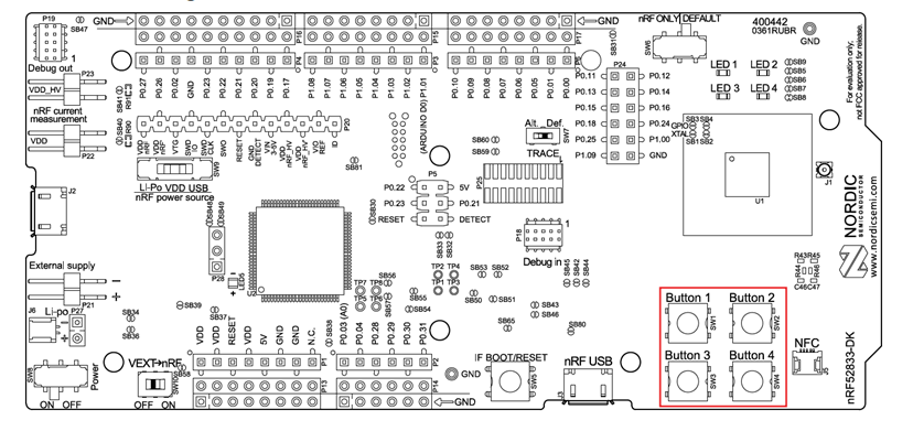
If we recall the schematic of the nRF52833 DK, there are four push-buttons connected to the same GPIO peripheral as the LEDs, GPIO0 (node label: gpio0). This can be seen in the GPIO pin mapping, for instance, notice that button 1 is connected to P0.11. The 0 in P0 symbolizes it is &gpio0.
nRF52833 DK button location
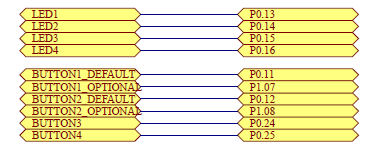
nRF52833 DK button pin mapping
This is why the same driver is needed for both the LEDs and buttons. This is also evident from the DK’s devicetree file nrf52833dk_nrf52833.dts.
Button 1 on the nRF52833 DK is given the node name button_0, which has the alias (sw0) and node label (button0) and is connected to &gpio0, pin 11. Remember, indexing in the devicetree files always starts from 0, which is why button 1 on the board is called button0.
If the buttons are connected to a different GPIO port (e.g. gpio1) than the LEDs, a new device pointer is required. As an example, the nRF54L15 DK, which has LEDs on both gpio1 and gpio2, while buttons are connected to gpio0 and gpio1.
Exercise steps
1. Clone the nRF Connect SDK Fundamentals GitHub repository. Note that the repository contains the exercise code base and solutions. Make sure to select the branch that corresponds with the nRF Connect SDK version of your choosing:
main (default branch): For nRF Connect SDK version v3.2.0
We have two options here. We can clone the GitHub repository using the graphical user interface in VS Code (described in step 1.1) or the command line (described in step 1.2). Pick either 1.1 or 1.2.
1.1 Copy the link to the repository and use VS Code’s Command Palette to clone the repository.
Go to View -> Command Palette -> type Git Clone and paste in the repository link. Save the repo somewhere close to the root directory.
1.2 Or, create a folder close to your root directory and clone the repository by running the following command in nRF Connect Terminal (In VS Code, open the Terminal via View → Terminal (or Ctrl+J), then click the Launch Profile… drop-down (arrow next to +) and select nRF Connect).
Once you issue the command, the course code base will be cloned in the current working directory.
Note
Ensure there are no spaces or other special characters in the path to the repository.
2. Open the exercise code base for this exercise in VS Code.
2.1 From the Welcome View in the nRF Connect extension, click on Open an existing application.
Select the base code for this exercise, found in l2/l2_e1 of whichever version you are using, and click on Select Folder.
2.2 Open main.c from the Explorer in VS Code as shown in the screenshot below:
3. Initialize the button on the hardware.
3.1 Get the node identifier for button 1 through its alias sw0.
Recall from the Devicetree section, that the /aliases node in the DK devicetree defined the alias sw0 for node &button0. The line below uses the macro call DT_ALIAS() to access the node identifier for the node through its alias.
In main.c , search for STEP 3.1 and add (copy and paste) the following lines:
Copy
#define SW0_NODE DT_ALIAS(sw0)
C
This is done to ensure compatibility across different hardware.
3.2 Get the device pointer, pin number and pin’s configuration flags through gpio_dt_spec.
The GPIO API has the struct called gpio_dt_spec that encapsulates all this information, and can be retrieved using GPIO_DT_SPEC_GET().
In main.c , search for STEP 3.2 and add (copy and paste) the following lines:
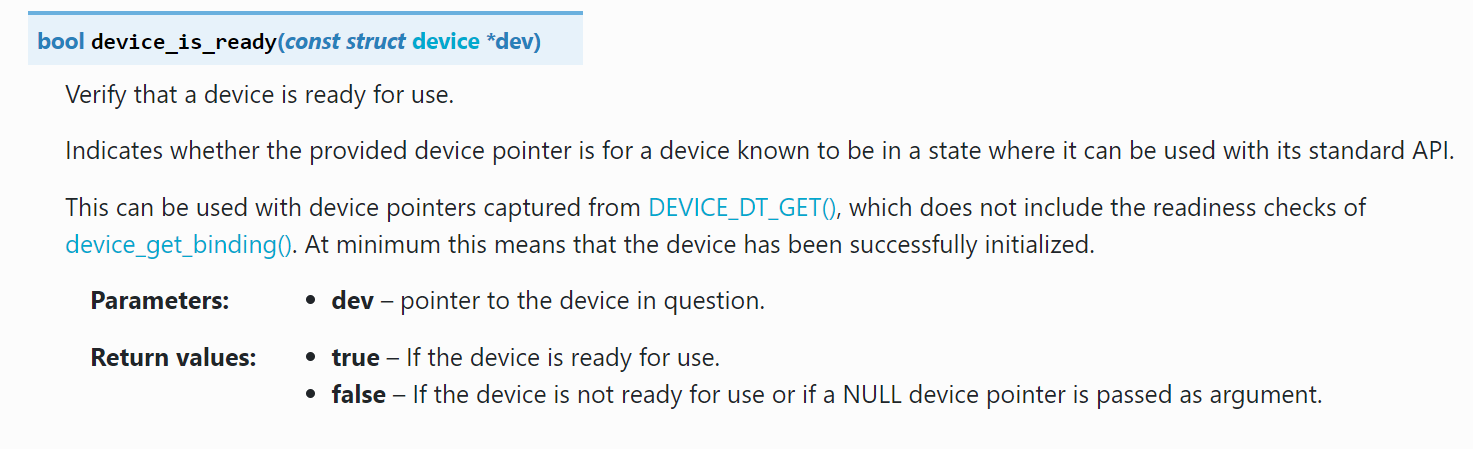
In main.c , search for STEP 4 and add (copy and paste) the following lines:
Copy
if (!device_is_ready(button.port)) {return -1;}
C
5. Configure the pin connected to the button to be an input pin and set its hardware specifications.
Inside main(), search for STEP 5 and add the following lines:
Copy
ret = gpio_pin_configure_dt(&button, GPIO_INPUT);if (ret < 0) {return -1;}
C
6. In the main loop of our exercise, we will indefinitely poll the CPU to read the status of the button (pressed = 1, unpressed = 0) and update the LED to the status of the button.
6.1 Read the status of the button and store it.
Using gpio_pin_get_dt(), read the current status of button.pin and save it in the variable val.
Search for STEP 6.1 and add the following code inside the infinite loop:
Copy
bool val = gpio_pin_get_dt(&button);
C
6.2 Update the LED to the status of the button
Update the LED to reflect the current status of the button that was saved in the variable val in the previous step, using gpio_pin_set_dt().
Search for STEP 6.2 and add the following code inside the infinite loop:
Copy
gpio_pin_set_dt(&led,val);
C
7. Change the sleep time from 1000 ms to 100 ms. 100 ms is about the right time to put the main thread to sleep and still be able to respond in time when the button is pressed.
9. Build the exercise and flash it to the board as we have done in the previous lesson. Observe that when button 1 is pressed, LED1 is turned ON. (Remember on the nRF54L15 DK that would be button0 and LED0)
The solution for this exercise can be found in the GitHub repository, in l2/l2_e1_sol of whichever version you are using.
Nordic Developer Academy Privacy Policy
1. IntroductionÂ
In this Privacy Policy you will find information on Nordic Semiconductor ASA (“Nordic Semiconductorâ€) processes your personal data when you use the Nordic Developer Academy.
References to “we†and “us†in this document refers to Nordic Semiconductor.
2. Our processing of personal data when you use the Nordic Developer AcademyÂ
2.1 Nordic Developer AcademyÂ
Nordic Semiconductor processes personal data in order to provide you with the features and functionality of the Nordic Developer Academy. Creating a user account is optional, but required if you want to track you progress and view your completed courses and obtained certificates. If you choose to create a user account, we will process the following categories of personal data:
Email
Name
Password (encrypted)
Course progression (e.g. which course you have completely or partly completed)
Certificate information, which consists of name of completed course and the validity of the certificate
Course results
During your use of the Nordic Developer Academy, you may also be asked if you want to provide feedback. If you choose to respond to any such surveys, we will also process the personal data in your responses in that survey.
The legal basis for this processing is GDPR article 6 (1) b. The processing is necessary for Nordic Semiconductor to provide the Nordic Developer Academy under the Terms of Service.
2.2 AnalyticsÂ
If you consent to analytics, Nordic Semiconductor will use Google Analytics to obtain statistics about how the Nordic Developer Academy is used. This includes collecting information on for example what pages are viewed, the duration of the visit, the way in which the pages are maneuvered, what links are clicked, technical information about your equipment. The information is used to learn how Nordic Developer Academy is used and how the user experience can be further developed.
2.2 NewsletterÂ
You can consent to receive newsletters from Nordic from within the Nordic Developer Academy. How your personal data is processed when you sign up for our newsletters is described in the Nordic Semiconductor Privacy Policy.
3. Retention periodÂ
We will store your personal data for as long you use the Nordic Developer Academy. If our systems register that you have not used your account for 36 months, your account will be deleted.
4. Additional informationÂ
Additional information on how we process personal data can be found in the Nordic Semiconductor Privacy Policy and Cookie Policy.
â€â€Â
Nordic Developer Academy Terms of Service
1. Introduction
â€These terms and conditions (“Terms of Useâ€) apply to the use of the Nordic Developer Academy, provided by Nordic Semiconductor ASA, org. nr. 966 011 726, a public limited liability company registered in Norway (“Nordic Semiconductorâ€). â€
Nordic Developer Academy allows the user to take technical courses related to Nordic Semiconductor products, software and services, and obtain a certificate certifying completion of these courses. By completing the registration process for the Nordic Developer Academy, you are agreeing to be bound by these Terms of Use.
These Terms of Use are applicable as long as you have a user account giving you access to Nordic Developer Academy.â€
â€2. Access to and use of Nordic Developer Academy
â€â€Upon acceptance of these Terms of Use you are granted a non-exclusive right of access to, and use of Nordic Developer Academy, as it is provided to you at any time. Nordic Semiconductor provides Nordic Developer Academy to you free of charge, subject to the provisions of these Terms of Use and the Nordic Developer Academy Privacy Policy.
To access select features of Nordic Developer Academy, you need to create a user account. You are solely responsible for the security associated with your user account, including always keeping your login details safe.
You will able to receive an electronic certificate from Nordic Developer Academy upon completion of courses. By issuing you such a certificate, Nordic Semiconductor certifies that you have completed the applicable course, but does not provide any further warrants or endorsements for any particular skills or professional qualifications.
Nordic Semiconductor will continuously develop Nordic Developer Academy with new features and functionality, but reserves the right to remove or alter any existing functions without notice.
â€3. Acceptable use
You undertake that you will use Nordic Developer Academy in accordance with applicable law and regulations, and in accordance with these Terms of Use.†You must not modify, adapt, or hack Nordic Developer Academy or modify another website so as to falsely imply that it is associated with Nordic Developer Academy, Nordic Semiconductor, or any other Nordic Semiconductor product, software or service.
You agree not to reproduce, duplicate, copy, sell, resell or in any other way exploit any portion of Nordic Developer Academy, use of Nordic Developer Academy, or access to Nordic Developer Academy without the express written permission by Nordic Semiconductor. You must not upload, post, host, or transmit unsolicited email, SMS, or \”spam\” messages.
You are responsible for ensuring that the information you post and the content you share does not;
contain false, misleading or otherwise erroneous information
infringe someone else’s copyrights or other intellectual property rights
contain sensitive personal data or
contain information that might be received as offensive or insulting.
Such information may be removed without prior notice.
â€Nordic Semiconductor reserves the right to at any time determine whether a use of Nordic Developer Academy is in violation of its requirements for acceptable use.
Violation of the at any time applicable requirements for acceptable use may result in termination of your account. We will take reasonable steps to notify you and state the reason for termination in such cases.
â€4. Routines for planned maintenance
â€Certain types of maintenance may imply a stop or reduction in availability of Nordic Developer Academy. Nordic Semiconductor does not warrant any level of service availability but will provide its best effort to limit the impact of any planned maintenance on the availability of Nordic Developer Academy.
5. Intellectual property rights
â€Nordic Semiconductor retains all rights to all elements of Nordic Developer Academy. This includes, but is not limited to, the concept, design, trademarks, know-how, trade secrets, copyrights and all other intellectual property rights.
Nordic Semiconductor receives all rights to all content uploaded or created in Nordic Developer Academy. You do not receive any license or usage rights to Nordic Developer Academy beyond what is explicitly stated in this Agreement.
â€6. Liability and damages
â€Nothing within these Terms of Use is intended to limit your statutory data privacy rights as a data subject, as described in the Nordic Developer Academy Privacy Policy. â€You acknowledge that errors might occur from time to time and waive any right to claim for compensation as a result of errors in Nordic Developer Academy. When an error occurs, you shall notify Nordic Semiconductor of the error and provide a description of the error situation.
You agree to indemnify Nordic Semiconductor for any loss, including indirect loss, arising out of or in connection with your use of Nordic Developer Academy or violations of these Terms of Use. â€Nordic Semiconductor shall not be held liable for, and does not warrant that (i) Nordic Developer Academy will meet your specific requirements, (ii) Nordic Developer Academy will be uninterrupted, timely, secure, or error-free, (iii) the results that may be obtained from the use of Nordic Developer Academy will be accurate or reliable, (iv) the quality of any products, services, information, or other material purchased or obtained by you through Nordic Developer Academy will meet your expectations, or that (v) any errors in Nordic Developer Academy will be corrected.
You accept that this is a service provided to you without any payment and hence you accept that Nordic Semiconductor will not be held responsible, or liable, for any breaches of these Terms of Use or any loss connected to your use of Nordic Developer Academy. Unless otherwise follows from mandatory law, Nordic Semiconductor will not accept any such responsibility or liability.
â€7. Change of terms
â€Nordic Semiconductor may update and change the Terms of Use from time to time. Nordic Semiconductor will seek to notify you about significant changes before such changes come into force and give you a possibility to evaluate the effects of proposed changes. Continued use of Nordic Developer Academy after any such changes shall constitute your acceptance of such changes. You can review the current version of the Terms of Use at any time at https://academy.nordicsemi.com/terms-of-service/
â€8. Transfer of rights
â€Nordic Semiconductor is entitled to transfer its rights and obligation pursuant to these Terms of Use to a third party as part of a merger or acquisition process, or as a result of other organizational changes.
â€9. Third Party Services
â€â€To the extent Nordic Developer Academy facilitates access to services provided by a third party, you agree to comply with the terms governing such third party services. Nordic Semiconductor shall not be held liable for any errors, omissions, inaccuracies, etc. related to such third party services.
â€10. Dispute resolution
â€â€The Terms of Use and any other legally binding agreement between yourself and Nordic Semiconductor shall be subject to Norwegian law and Norwegian courts’ exclusive jurisdiction.
Switch language?
Progress is tracked separately for each language. Switching will continue from your progress in that language or start fresh if you haven't begun.
Your current progress is saved, and you can switch back anytime.
•This release includes Long-Term Support (LTS) for five years.
•Patch (minor) releases will address security vulnerabilities and critical bug fixes.
•API stability is guaranteed; breaking changes are only introduced when required by a security fix.
•Notifications for critical bug fixes and security updates via the myNordic notification system (mynordic.nordicsemi.com)
General updates
•Support for nRF54LS05 DK (Available through the early access sampling program) •Support for the nRF54LM20B with Axon NPU for Edge AI applications
Bluetooth LE updates
•Quality of Service module is now production-ready. •New experimental features for RF testing (Direct Test Mode) and low-latency packet handling (LE Flushable ACL).
MCUboot & Partition Manager
•Single-Slot DFU and RAM Load mode are both promoted to fully supported •Partition Manager is officially deprecated in favor of Zephyr's devicetree-based partitioning.
General updates
•Added comprehensive support for the nRF54L Series. •Bug fixes and improvements. •Hardware model v1, which was deprecated in nRF Connect SDK 2.7.0, has now been removed. •Multi-image builds functionality (parent-child images), which was deprecated in nRF Connect SDK v2.7.0 has now been removed.
Bluetooth LE updates
•Added support for Bluetooth Core version 6.2. •Added support for Bluetooth LE Shorter Connection Intervals. •Added support for Bluetooth LE Channel Sounding.
Bootloader updates
•Support for MCUboot image compression. •Single slot DFU support for the nRF54L Series. •Encrypted DFU support using ECIES on the nRF54L15, nRF54LM20, and nRF54LV10 SoCs.