In Zephyr, there are three different ways to access the UART peripheral, all with different API functions; polling, interrupt-driven and asynchronous. In this lesson, we will be covering the asynchronous API.
The Asynchronous API is the most efficient way to use UART. It allows you to read and write data in the background using EasyDMA. In addition, the asynchronous mode supports features that allow us to enable receive timeouts and control the amount of data received before an interrupt is triggered. The asynchronous API is quite powerful and covers most use-cases.
Polling is the most basic method to access the UART peripheral. The reading function, uart_poll_in(), is a non-blocking function and returns a character or -1 when no valid data is available. The writing function, uart_poll_out(), is a blocking function and the thread waits until the given character is sent. We will not cover the method in this course. With the Interrupt-driven API (raw interrupts), the UART driver ISR will manage the data, while the user application can continue other tasks. The Kernel’s Data Passing features (f.ex FIFO) can be used to communicate between the user application and the UART driver. We will not cover the method in this course.
1. As always, when it comes to drivers, the first thing we need to do is to enable the serial driver (UART driver). This is done by adding these two lines in prj.conf.
Copy
CONFIG_SERIAL=yCONFIG_UART_ASYNC_API=y
Kconfig
The first line is usually enabled by default through the board’s devicetree as we have seen in-depth in Lesson 2. However, the second line is important to enable the asynchronous API of the serial driver.
2. Include the header file of the UART driver in your source code.
Copy
#include<zephyr/drivers/uart.h>
C
3. As we have seen in the previous lessons, a peripheral (GPIO, UART, I2C, SPI, etc.) is instantiated as a device pointer, which is a structure to hold information about the peripheral in a standard way.
Some drivers in Zephyr have API-specific structures and calls that encapsulate all the information needed to control the device in one structure. The UART driver does not have this, so we will use the macro call DEVICE_DT_GET() that was covered in the Device driver model section.
The pointer uart of type struct device is the structure that is used when interacting with the UART API.
On the other hand, uart0 is the node label of the devicetree node that represents the UART hardware controller on the chip.
Information about the nodes and node names can also be obtained in VS Code in the Devicetree Visual Editor.
Note that this is only available after you build your nRF Connect SDK application, and you must select a specific image, not the full build (sysbuild). We will take a closer look at the Devicee Visual Editor in Exercise 1 of this lesson.
One more thing to notice in the devicetree is that the default speed (baud rate) is set to 115200.
UART Configurations
1. UART configurations like baudrate and parity bit can be configured both statically at build time and dynamically at run time as the Kconfig option (CONFIG_UART_USE_RUNTIME_CONFIGURE) is enabled by default.
Recall
It is also possible to change these configurations using the Devicetree. We covered how to change the UART configurations through the Devicetree Visual Editor in Lesson 3 Exercise 1.
The default static configuration of the UART hardware is obtained from the devicetree as we have seen in the previous step.
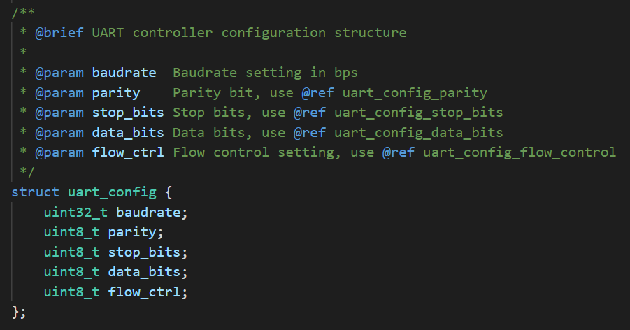
On the other hand, to change the UART configurations dynamically, you need to create a variable of type uart_config.
uart_config struct
An example of creating a variable of type uart_config is shown below:
A callback function (also known as an interrupt handler or an ISR) runs asynchronously in response to a hardware or software interrupt. In general, ISRs have a higher priority than all threads (covered in Lesson 7). It preempts the execution of the current thread, allowing an action to take place immediately. Thread execution resumes only once all ISR work has been finished. Always try to keep the ISR as short as possible to guarantee your system’s responsiveness and prevent thread starvation.
We have the freedom to choose which UART events of interest to listen to.
Below are the available UART events:
Event
Description
UART_TX_DONE
The whole TX buffer was transmitted
UART_TX_ABORTED
Transmitting aborted due to timeout or uart_tx_abort() call
UART_RX_RDY
Some data was received and receive timeout occurred (if RX timeout is enabled) or when the receive buffer is full
UART_RX_BUF_REQUEST
Driver requests next buffer for continuous reception
UART_RX_BUF_RELEASED
Buffer is no longer used by UART driver
UART_RX_DISABLED
This event is generated whenever receiver has been stopped, disabled or finished its operation (receive buffer filled) and can be enabled again using uart_rx_enable()
UART_RX_STOPPED
RX has stopped due to external event
Types of events passed to callback in UART_ASYNC_API Type uart_event_type
The callback function should have the following signature:
Copy
staticvoiduart_cb(conststruct device *dev, struct uart_event *evt, void *user_data){switch (evt->type) {case UART_TX_DONE:// do somethingbreak;case UART_TX_ABORTED:// do somethingbreak;case UART_RX_RDY:// do somethingbreak;case UART_RX_BUF_REQUEST:// do somethingbreak;case UART_RX_BUF_RELEASED:// do somethingbreak;case UART_RX_DISABLED:// do somethingbreak;case UART_RX_STOPPED:// do somethingbreak;default:break; }}
C
We do not have to include all of these switch cases. Only include the ones relevant to your application code as we will see in the exercise section of this lesson.
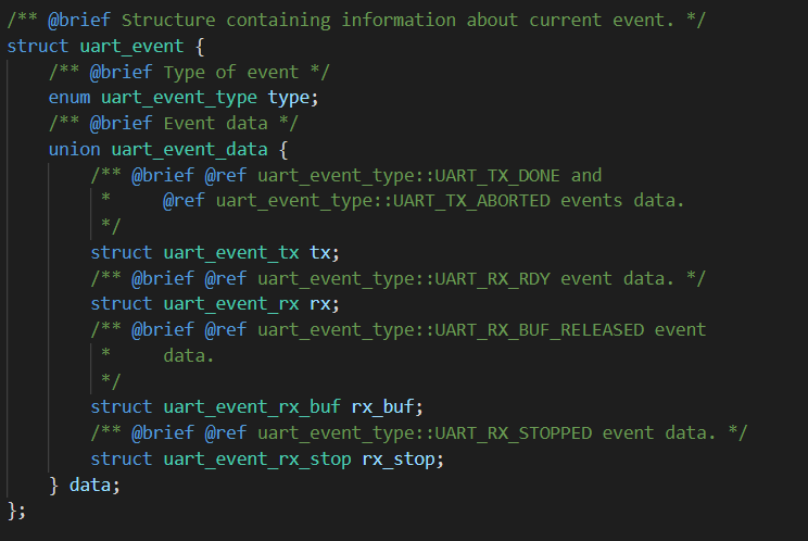
uart_event struct
The uart_event struct contains the UART event type and a union, which could be one of the four members (tx, rx , rx_buf, rx_stop).
The rx member is of type uart_event_rx, which will hold the incoming data over UART.
uart_event_rx struct
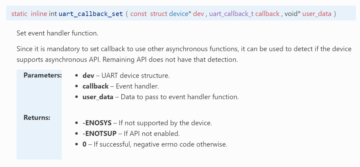
3. Register the callback function by calling the function uart_callback_set(), which takes three parameters as shown in the screenshot below:
In this part, we will explain the needed steps to start receiving data over UART using the asynchronous API of the UART driver.
1. Declare a receive buffer to store the incoming data. The size and the type of the buffer must be selected with your application requirements in mind. For the simple exercises we have in this lesson, which controls LEDs through UART, we will simply declare a buffer of type uint8_t (a byte) of size 10 bytes. In future lessons, we will introduce some more capable data structures (FIFO, circular buffer, etc.) that can be used to store the incoming data with more flexibility.
Copy
staticuint8_trx_buf[10] = {0}; //A buffer to store incoming UART data
C
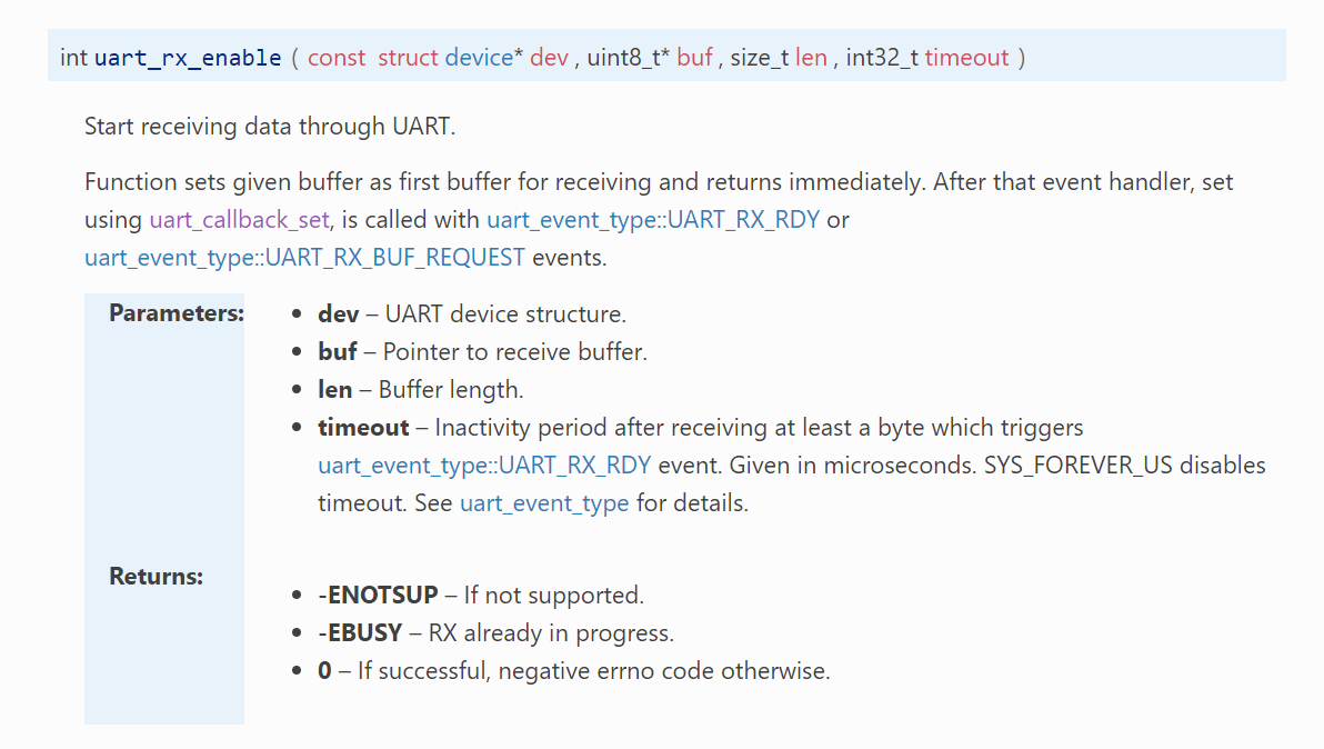
2. To start receiving, call the uart_rx_enable()function, and pass the address of the receive buffer.
The last parameter is the timeout, which in the context of the uart_rx_enable() function will determine how fast we get notified on incoming data that is less than the whole buffer size. It is called the inactivity period, which is measured after receiving at least a byte. Pick a value that fits your application’s requirements. You can also disable the timeout by passing SYS_FOREVER_US.
uart_rx_enable() signature
Note that this function returns immediately. Inside the UART ISR we can do (or delegate) the work of copying received data to the specified receive buffer.
3. The data received is accessible through the UART callback on the UART_RX_RDY event.
Item
How to access it
Data Length
evt->data.rx.len
Offset to where in the buffer data is stored
evt->data.rx.offset
Actual data received
evt->rx.buf[rx.offset] to evt->rx.buf[rx.offset+rx.len]
4. Continuous reception is not enabled by default, which means once the receive buffer is full, you must manually enable reception. Inside the UART_RX_DISABLED case of the UART callback, you must re-enable UART to have continuous reception, like below:
Copy
case UART_RX_DISABLED:uart_rx_enable(dev, rx_buf, sizeof(rx_buf), 100);break;
C
Note
The UART asynchronous API offers a way to perform chained buffer reception. You can declare multiple buffers to seamlessly switch between them when the current buffer is full. To do this you need to call uart_rx_buf_rsp() on the event UART_RX_BUF_REQUEST, which will provide the next buffer. When the current buffer is filled, receiving will automatically go to the next buffer.
Transmitting
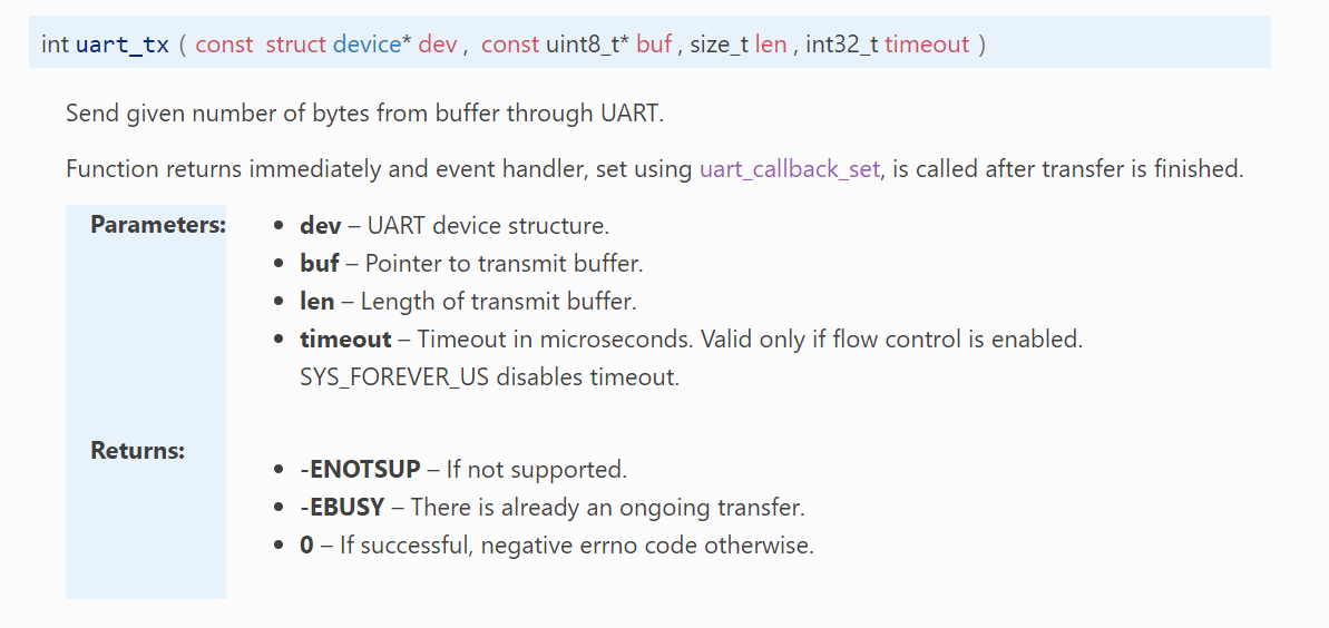
Transmitting is a straightforward task as we only need to specify the transmission buffer.
1. Define a transmission buffer to hold the data to be sent. The size and the type of the buffer must be selected with your application requirements in mind. In the exercise section, we will simply send a welcome message. Therefore we will define the transmission buffer to be of type uint8_t.
The function returns immediately and the sending is actually managed internally by the UART driver.
(Optional) 3. If your application needs to take action once the whole transmission buffer is transmitted, you could do that by using the UART_TX_DONE event in the UART callback function.
Copy
case UART_TX_DONE:// Do something here if needed break;
C
Nordic Developer Academy Privacy Policy
1. Introduction
In this Privacy Policy you will find information on Nordic Semiconductor ASA (“Nordic Semiconductor”) processes your personal data when you use the Nordic Developer Academy.
References to “we” and “us” in this document refers to Nordic Semiconductor.
2. Our processing of personal data when you use the Nordic Developer Academy
2.1 Nordic Developer Academy
Nordic Semiconductor processes personal data in order to provide you with the features and functionality of the Nordic Developer Academy. Creating a user account is optional, but required if you want to track you progress and view your completed courses and obtained certificates. If you choose to create a user account, we will process the following categories of personal data:
Email
Name
Password (encrypted)
Course progression (e.g. which course you have completely or partly completed)
Certificate information, which consists of name of completed course and the validity of the certificate
Course results
During your use of the Nordic Developer Academy, you may also be asked if you want to provide feedback. If you choose to respond to any such surveys, we will also process the personal data in your responses in that survey.
The legal basis for this processing is GDPR article 6 (1) b. The processing is necessary for Nordic Semiconductor to provide the Nordic Developer Academy under the Terms of Service.
2.2 Analytics
If you consent to analytics, Nordic Semiconductor will use Google Analytics to obtain statistics about how the Nordic Developer Academy is used. This includes collecting information on for example what pages are viewed, the duration of the visit, the way in which the pages are maneuvered, what links are clicked, technical information about your equipment. The information is used to learn how Nordic Developer Academy is used and how the user experience can be further developed.
2.2 Newsletter
You can consent to receive newsletters from Nordic from within the Nordic Developer Academy. How your personal data is processed when you sign up for our newsletters is described in the Nordic Semiconductor Privacy Policy.
3. Retention period
We will store your personal data for as long you use the Nordic Developer Academy. If our systems register that you have not used your account for 36 months, your account will be deleted.
4. Additional information
Additional information on how we process personal data can be found in the Nordic Semiconductor Privacy Policy and Cookie Policy.
Nordic Developer Academy Terms of Service
1. Introduction
These terms and conditions (“Terms of Use”) apply to the use of the Nordic Developer Academy, provided by Nordic Semiconductor ASA, org. nr. 966 011 726, a public limited liability company registered in Norway (“Nordic Semiconductor”).
Nordic Developer Academy allows the user to take technical courses related to Nordic Semiconductor products, software and services, and obtain a certificate certifying completion of these courses. By completing the registration process for the Nordic Developer Academy, you are agreeing to be bound by these Terms of Use.
These Terms of Use are applicable as long as you have a user account giving you access to Nordic Developer Academy.
2. Access to and use of Nordic Developer Academy
Upon acceptance of these Terms of Use you are granted a non-exclusive right of access to, and use of Nordic Developer Academy, as it is provided to you at any time. Nordic Semiconductor provides Nordic Developer Academy to you free of charge, subject to the provisions of these Terms of Use and the Nordic Developer Academy Privacy Policy.
To access select features of Nordic Developer Academy, you need to create a user account. You are solely responsible for the security associated with your user account, including always keeping your login details safe.
You will able to receive an electronic certificate from Nordic Developer Academy upon completion of courses. By issuing you such a certificate, Nordic Semiconductor certifies that you have completed the applicable course, but does not provide any further warrants or endorsements for any particular skills or professional qualifications.
Nordic Semiconductor will continuously develop Nordic Developer Academy with new features and functionality, but reserves the right to remove or alter any existing functions without notice.
3. Acceptable use
You undertake that you will use Nordic Developer Academy in accordance with applicable law and regulations, and in accordance with these Terms of Use. You must not modify, adapt, or hack Nordic Developer Academy or modify another website so as to falsely imply that it is associated with Nordic Developer Academy, Nordic Semiconductor, or any other Nordic Semiconductor product, software or service.
You agree not to reproduce, duplicate, copy, sell, resell or in any other way exploit any portion of Nordic Developer Academy, use of Nordic Developer Academy, or access to Nordic Developer Academy without the express written permission by Nordic Semiconductor. You must not upload, post, host, or transmit unsolicited email, SMS, or \”spam\” messages.
You are responsible for ensuring that the information you post and the content you share does not;
contain false, misleading or otherwise erroneous information
infringe someone else’s copyrights or other intellectual property rights
contain sensitive personal data or
contain information that might be received as offensive or insulting.
Such information may be removed without prior notice.
Nordic Semiconductor reserves the right to at any time determine whether a use of Nordic Developer Academy is in violation of its requirements for acceptable use.
Violation of the at any time applicable requirements for acceptable use may result in termination of your account. We will take reasonable steps to notify you and state the reason for termination in such cases.
4. Routines for planned maintenance
Certain types of maintenance may imply a stop or reduction in availability of Nordic Developer Academy. Nordic Semiconductor does not warrant any level of service availability but will provide its best effort to limit the impact of any planned maintenance on the availability of Nordic Developer Academy.
5. Intellectual property rights
Nordic Semiconductor retains all rights to all elements of Nordic Developer Academy. This includes, but is not limited to, the concept, design, trademarks, know-how, trade secrets, copyrights and all other intellectual property rights.
Nordic Semiconductor receives all rights to all content uploaded or created in Nordic Developer Academy. You do not receive any license or usage rights to Nordic Developer Academy beyond what is explicitly stated in this Agreement.
6. Liability and damages
Nothing within these Terms of Use is intended to limit your statutory data privacy rights as a data subject, as described in the Nordic Developer Academy Privacy Policy. You acknowledge that errors might occur from time to time and waive any right to claim for compensation as a result of errors in Nordic Developer Academy. When an error occurs, you shall notify Nordic Semiconductor of the error and provide a description of the error situation.
You agree to indemnify Nordic Semiconductor for any loss, including indirect loss, arising out of or in connection with your use of Nordic Developer Academy or violations of these Terms of Use. Nordic Semiconductor shall not be held liable for, and does not warrant that (i) Nordic Developer Academy will meet your specific requirements, (ii) Nordic Developer Academy will be uninterrupted, timely, secure, or error-free, (iii) the results that may be obtained from the use of Nordic Developer Academy will be accurate or reliable, (iv) the quality of any products, services, information, or other material purchased or obtained by you through Nordic Developer Academy will meet your expectations, or that (v) any errors in Nordic Developer Academy will be corrected.
You accept that this is a service provided to you without any payment and hence you accept that Nordic Semiconductor will not be held responsible, or liable, for any breaches of these Terms of Use or any loss connected to your use of Nordic Developer Academy. Unless otherwise follows from mandatory law, Nordic Semiconductor will not accept any such responsibility or liability.
7. Change of terms
Nordic Semiconductor may update and change the Terms of Use from time to time. Nordic Semiconductor will seek to notify you about significant changes before such changes come into force and give you a possibility to evaluate the effects of proposed changes. Continued use of Nordic Developer Academy after any such changes shall constitute your acceptance of such changes. You can review the current version of the Terms of Use at any time at https://academy.nordicsemi.com/terms-of-service/
8. Transfer of rights
Nordic Semiconductor is entitled to transfer its rights and obligation pursuant to these Terms of Use to a third party as part of a merger or acquisition process, or as a result of other organizational changes.
9. Third Party Services
To the extent Nordic Developer Academy facilitates access to services provided by a third party, you agree to comply with the terms governing such third party services. Nordic Semiconductor shall not be held liable for any errors, omissions, inaccuracies, etc. related to such third party services.
10. Dispute resolution
The Terms of Use and any other legally binding agreement between yourself and Nordic Semiconductor shall be subject to Norwegian law and Norwegian courts’ exclusive jurisdiction.
Switch language?
Progress is tracked separately for each language. Switching will continue from your progress in that language or start fresh if you haven't begun.
Your current progress is saved, and you can switch back anytime.
•This release includes Long-Term Support (LTS) for five years.
•Patch (minor) releases will address security vulnerabilities and critical bug fixes.
•API stability is guaranteed; breaking changes are only introduced when required by a security fix.
•Notifications for critical bug fixes and security updates via the myNordic notification system (mynordic.nordicsemi.com)
General updates
•Support for nRF54LS05 DK (Available through the early access sampling program) •Support for the nRF54LM20B with Axon NPU for Edge AI applications
Bluetooth LE updates
•Quality of Service module is now production-ready. •New experimental features for RF testing (Direct Test Mode) and low-latency packet handling (LE Flushable ACL).
MCUboot & Partition Manager
•Single-Slot DFU and RAM Load mode are both promoted to fully supported •Partition Manager is officially deprecated in favor of Zephyr's devicetree-based partitioning.
General updates
•Added comprehensive support for the nRF54L Series. •Bug fixes and improvements. •Hardware model v1, which was deprecated in nRF Connect SDK 2.7.0, has now been removed. •Multi-image builds functionality (parent-child images), which was deprecated in nRF Connect SDK v2.7.0 has now been removed.
Bluetooth LE updates
•Added support for Bluetooth Core version 6.2. •Added support for Bluetooth LE Shorter Connection Intervals. •Added support for Bluetooth LE Channel Sounding.
Bootloader updates
•Support for MCUboot image compression. •Single slot DFU support for the nRF54L Series. •Encrypted DFU support using ECIES on the nRF54L15, nRF54LM20, and nRF54LV10 SoCs.