Exercise 1 – Connecting an BME280 temperature sensor
Connecting a BME280 temperature sensor
In this exercise, we will use a BME280 Sensor hosted on a Waveshare 15231 board to provide temperature readings. We chose a breakout board that supports I2C and SPI communication protocols to use the sensor in multiple lessons. The image below shows the BME280 module and the breakout board.
Waveshare 15231 board
Note
This exercise is not supported on the Thingy. If you are using the Thingy prototyping platform (Thingy:53, Thingy:91, Thingy:91 X), please see Exercise 2 of this lesson.
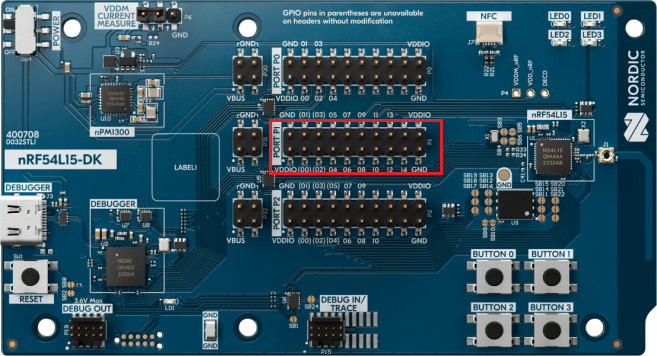
The Waveshare 15231 board can easily be attached to any of our development kits through one of the available pin header connectors. The sensor board should be connected to the DK board (nRF54L15 in this case) using the P1 connector. Pin P1.11 will be configured as SCL, and P1.12 as SDA. VDDIO and GND should be connected as VCC and GND to the sensor board.
P1 connector on nRF54L15DK board
The BME280 sensor offers three sensor modes: sleep mode, forced mode, and normal mode. After powering up the sensor, it will go into sleep mode by default. We should configure the sensor to go to normal or forced mode after powering up. That is to say, we need to configure the sensor’s mode bits before reading the values.
The entire communication with the BME280 is performed by reading and writing to registers that are 8-bit wide. The memory map of BME280 is shown below:
BME280 register memory map
Some registers are reserved and should not be changed. The calibration data is read-only, as these values are fixed at the time of production. Control registers are read-write capable and are used to control the settings. Data registers are the values returned or stored by the sensor after performing the sensing operation and, hence, are read-only. Status and chip-id are also read-only, while reset is write-only.
Data registers provide a 20-bit pressure value, a 20-bit temperature value, and a 16-bit humidity value. As all registers are 8-bit wide, we will perform a multiple-byte read operation and then construct the value by putting bits/bytes at their proper locations. To read out the data values after conversion, it is recommended to use a burst mode and not address every register individually. Data readout is done by starting a burst read from 0xF7 to 0xFC (for temperature and pressure) or from 0xF7 to 0xFE (for temperature, pressure, and humidity).
The data is read out in an unsigned 20-bit format both for temperature and pressure and an unsigned 16-bit format for humidity. These readout values represent the uncompensated measurements. The actual temperature, pressure, and humidity values are then calculated using the compensation parameters. These compensation parameters are stored in the non-volatile memory of the device at the time of production. The register address, the content, and the datatype for these compensation parameters are shown in the table below.
1. In the GitHub repository for this course, open the base code for this exercise, found in l6/l6_e1. Note that the BME280 sensor is used in v2.7.0 and above.
2. Let’s enable the I2C driver by adding the following line to the application configuration file prj.conf.
Copy
CONFIG_I2C=y
Kconfig
3. In main.c , include the header file of the I2C API.
Copy
#include<zephyr/drivers/i2c.h>
C
4. To display the sensor readings on the console, we will use a simple printk().
4.1 Include the header file <sys/printk.h> to use printk().
Copy
#include<zephyr/sys/printk.h>
C
4.2 Add the following configuration option to prj.conf to enable support for floating-point format specifiers, so we can print the temperature readings as floats. The reason why this option is not enabled by default is to save memory space, as enabling this option would increase code size by at least 1Kbytes.
Copy
CONFIG_CBPRINTF_FP_SUPPORT=y
Kconfig
5. Devicetree preparations
5.1 Create a folder called “boards” and place it in this exercise’s directory as shown below.
5.2 Add an overlay file for the board
Note
If you are using a development kit other than the nRF54L15DK, please use the appropriate overlay content from the tabs below and name the overlay file according to your specific board target.
Since the sensor is external to the board, we must add an overlay file to specify this external sensor is a child to which i2c node and specify the sensor’s address. We also need to enable the i2c node and configure the pins.
As we explained in the previous topic (I2C Driver), create an overlay file, name in [board]_[soc].overlay form (For the nRF54L15 DK, it will be nrf54l15dk_nrf54l15_cpuapp.overlay) and add the following code in the overlay file. How we got it 0x77 is explained in step 5.3.
When adding an overlay file to an application, a pristine build must be run before flashing. A warning in VS Code will pop up asking if you want to run the pristine build now.
5.3 The 7-bit device address is 111011x. The 6 MSB bits are fixed. The last bit is changeable by SDO value (see bme280 datasheet ) and can be changed during operation. Connecting SDO to GND results in slave address 1110110 (0x76); connection it to VDD/VDDIO results in slave address 1110111 (0x77), which is the same as BMP280’s I²C address.
The SDO Pin is represented by ADDR/MISO on the Waveshare 15231 board. This pin is pulled up, so if the connection is unchanged, the SDO in the BME280 will remain high, giving a 0x77 address
Waveshare 15231 board ADDR/MISO pin.
Some sensor vendors offer 8-bit addresses that include the read/write bit. To identify this, they usually provide separate addresses for writing and reading. In such cases, only the top seven bits of the address should be used.
6. Get the sensor’s node identifier. This was explained in detail in step 4 of the I2C Driver section.
Copy
#define I2C_NODE DT_NODELABEL(mysensor)
C
7. Retrieve the API-specific device structure and make sure that the device is ready to use:
Copy
staticconststruct i2c_dt_spec dev_i2c = I2C_DT_SPEC_GET(I2C_NODE);if (!device_is_ready(dev_i2c.bus)) {printk("I2C bus %s is not ready!\n\r",dev_i2c.bus->name);return -1;}
C
With this, we have the pointer to the device structure of the I2C controller and the sensor address (target device address) and can start using the I2C driver API to configure the sensor connected to the I2C controller.
8. Define the addresses of the relevant registers (from the sensor datasheet). Typically this information goes into a separate header file (.h). However, for the sake of keeping this demonstration simple, we will add them in main.c.
Copy
#define CTRLMEAS 0xF4#define CALIB00 0x88#define ID 0xD0#define TEMPMSB 0xFA
C
9. We verify that we have properly connected the sensor by reading the chip ID. When the value is correct (see bme280 datasheet), we know that the sensor is working properly, and we can take the next step – Read Calibration registers
Copy
uint8_t id = 0;uint8_t regs[] = {ID};int ret = i2c_write_read_dt(&dev_i2c, regs, 1, &id, 1);if (ret != 0) {printk("Failed to read register %x\n", regs[0]);return -1; }if (id != CHIP_ID) {printk("Invalid chip id! %x\n", id);return -1; }
10. Read Calibration Registers. Most of the compensation parameters are 2-byte values. In this case, we read temperature compensation parameter registers (2B each) in burst mode.
Temperature compensation parameters begin from 0x88 address and contain 3 following registers.
Temperature calibration registers
Copy
uint8_tvalues[6];int ret = i2c_burst_read_dt(spec, CALIB00, values, 6);if (ret != 0) {printk("Failed to read register %x\n", CALIB00);return; }
After reading from register locations, we will put bits/bytes in their proper locations to form compensation parameter values.
These compensation parameters will be used by the compensation routines along with uncompensated environmental readings to make the correct / compensated outputs. Compensation formulas and routines are provided in the datasheet. Refer to the datasheet for more information. We use those routines as is with small modifications (in the prototype and variable datatypes).
11. Now we need to configure the sensor by writing to the configuration register. As per the datasheet, we have to put register into active/normal mode by setting MODE bits to b’11. And to set the oversampling parameters to b’100 (i.e. 8x oversampling), we have to 0x93 to the CTRLMEAS register. These registers are defined at the top of the main.c.
13. Connect the sensor board to your DK using jumper cables.
Wire color
Sensor board
nRF54L15 DK
Red
VCC
VDDIO by Port P1
Black
GND
GND by Port P1
Blue
SDA
Port P1.12
Yellow
SCL
Port P1.11
Connection for sensor board
Connection for DK
13.1 Configure the board to output the correct voltage.
In nRF Connect for Desktop, install and launch the Board Configurator. The Board Configurator is a desktop app that lets you adjust the settings of the “board controller” on Nordic Development Kits (DKs).
The board controller is firmware running on the DK’s Interface MCU, which controls the DK’s operation. Using the Board Configurator, you can easily change the DK’s configuration.
In the upper left-hand corner, click Select Device, and a drown-down menu will appear with all connected devices. Select the nRF54L15 DK.
Under VDD (nPM VOUT1), make sure 3.3V is selected. Then select Write config, to write the current configuration to the board. Now, the board will give the correct output voltage to power the shield.
13. Connect the sensor board to your DK using jumper cables.
Wire color
Sensor board
nRF52 DK
Red
VCC
VDD
Black
GND
GND
Blue
SDA
Port P0.25
Yellow
SCL
Port P0.24
13. Connect the sensor board to your DK using jumper cables.
Wire color
Sensor board
nRF52833 DK
Red
VCC
VDD
Black
GND
GND
Blue
SDA
Port P0.23
Yellow
SCL
Port P0.22
13. Connect the sensor board to your DK using jumper cables.
Wire color
Sensor board
nRF52840 DK
Red
VCC
VDD
Black
GND
GND
Blue
SDA
Port P1.15
Yellow
SCL
Port P1.14
13. Connect the sensor board to your DK using jumper cables.
Wire color
Sensor board
nRF5340 DK
Red
VCC
VDD
Black
GND
GND
Blue
SDA
Port P1.15
Yellow
SCL
Port P1.14
13. Connect the sensor board to your DK using jumper cables.
Wire color
Sensor board
nRF9160 DK
Red
VCC
VDD
Black
GND
GND
Blue
SDA
Port P0.13
Yellow
SCL
Port P0.12
13. Connect the sensor board to your DK using jumper cables.
Wire color
Sensor board
nRF7002 DK
Red
VCC
VDD
Black
GND
GND
Blue
SDA
Port P1.15
Yellow
SCL
Port P1.14
13. Connect the sensor board to your DK using jumper cables.
Wire color
Sensor board
nRF91x1 DK
Red
VCC
VDD
Black
GND
GND
Blue
SDA
Port P0.13
Yellow
SCL
Port P0.12
14. Build the application and flash it on your development kit.
Using a serial terminal, you should see the below output:
*** Booting nRF Connect SDK ***Temperature in Celsius : 26.37 CTemperature in Fahrenheit : 79.47 FTemperature in Celsius : 26.37 CTemperature in Fahrenheit : 79.47 FTemperature in Celsius : 26.37 CTemperature in Fahrenheit : 79.47 FTemperature in Celsius : 26.37 CTemperature in Fahrenheit : 79.36 FTemperature in Celsius : 26.37 CTemperature in Fahrenheit : 79.36 F
Terminal
Try blowing on the sensor, and notice an immediate change in the readings.
The solution for this exercise can be found in the GitHub repository, l6/l6_e1_sol.
Nordic Developer Academy Privacy Policy
1. Introduction
In this Privacy Policy you will find information on Nordic Semiconductor ASA (“Nordic Semiconductor”) processes your personal data when you use the Nordic Developer Academy.
References to “we” and “us” in this document refers to Nordic Semiconductor.
2. Our processing of personal data when you use the Nordic Developer Academy
2.1 Nordic Developer Academy
Nordic Semiconductor processes personal data in order to provide you with the features and functionality of the Nordic Developer Academy. Creating a user account is optional, but required if you want to track you progress and view your completed courses and obtained certificates. If you choose to create a user account, we will process the following categories of personal data:
Email
Name
Password (encrypted)
Course progression (e.g. which course you have completely or partly completed)
Certificate information, which consists of name of completed course and the validity of the certificate
Course results
During your use of the Nordic Developer Academy, you may also be asked if you want to provide feedback. If you choose to respond to any such surveys, we will also process the personal data in your responses in that survey.
The legal basis for this processing is GDPR article 6 (1) b. The processing is necessary for Nordic Semiconductor to provide the Nordic Developer Academy under the Terms of Service.
2.2 Analytics
If you consent to analytics, Nordic Semiconductor will use Google Analytics to obtain statistics about how the Nordic Developer Academy is used. This includes collecting information on for example what pages are viewed, the duration of the visit, the way in which the pages are maneuvered, what links are clicked, technical information about your equipment. The information is used to learn how Nordic Developer Academy is used and how the user experience can be further developed.
2.2 Newsletter
You can consent to receive newsletters from Nordic from within the Nordic Developer Academy. How your personal data is processed when you sign up for our newsletters is described in the Nordic Semiconductor Privacy Policy.
3. Retention period
We will store your personal data for as long you use the Nordic Developer Academy. If our systems register that you have not used your account for 36 months, your account will be deleted.
4. Additional information
Additional information on how we process personal data can be found in the Nordic Semiconductor Privacy Policy and Cookie Policy.
Nordic Developer Academy Terms of Service
1. Introduction
These terms and conditions (“Terms of Use”) apply to the use of the Nordic Developer Academy, provided by Nordic Semiconductor ASA, org. nr. 966 011 726, a public limited liability company registered in Norway (“Nordic Semiconductor”).
Nordic Developer Academy allows the user to take technical courses related to Nordic Semiconductor products, software and services, and obtain a certificate certifying completion of these courses. By completing the registration process for the Nordic Developer Academy, you are agreeing to be bound by these Terms of Use.
These Terms of Use are applicable as long as you have a user account giving you access to Nordic Developer Academy.
2. Access to and use of Nordic Developer Academy
Upon acceptance of these Terms of Use you are granted a non-exclusive right of access to, and use of Nordic Developer Academy, as it is provided to you at any time. Nordic Semiconductor provides Nordic Developer Academy to you free of charge, subject to the provisions of these Terms of Use and the Nordic Developer Academy Privacy Policy.
To access select features of Nordic Developer Academy, you need to create a user account. You are solely responsible for the security associated with your user account, including always keeping your login details safe.
You will able to receive an electronic certificate from Nordic Developer Academy upon completion of courses. By issuing you such a certificate, Nordic Semiconductor certifies that you have completed the applicable course, but does not provide any further warrants or endorsements for any particular skills or professional qualifications.
Nordic Semiconductor will continuously develop Nordic Developer Academy with new features and functionality, but reserves the right to remove or alter any existing functions without notice.
3. Acceptable use
You undertake that you will use Nordic Developer Academy in accordance with applicable law and regulations, and in accordance with these Terms of Use. You must not modify, adapt, or hack Nordic Developer Academy or modify another website so as to falsely imply that it is associated with Nordic Developer Academy, Nordic Semiconductor, or any other Nordic Semiconductor product, software or service.
You agree not to reproduce, duplicate, copy, sell, resell or in any other way exploit any portion of Nordic Developer Academy, use of Nordic Developer Academy, or access to Nordic Developer Academy without the express written permission by Nordic Semiconductor. You must not upload, post, host, or transmit unsolicited email, SMS, or \”spam\” messages.
You are responsible for ensuring that the information you post and the content you share does not;
contain false, misleading or otherwise erroneous information
infringe someone else’s copyrights or other intellectual property rights
contain sensitive personal data or
contain information that might be received as offensive or insulting.
Such information may be removed without prior notice.
Nordic Semiconductor reserves the right to at any time determine whether a use of Nordic Developer Academy is in violation of its requirements for acceptable use.
Violation of the at any time applicable requirements for acceptable use may result in termination of your account. We will take reasonable steps to notify you and state the reason for termination in such cases.
4. Routines for planned maintenance
Certain types of maintenance may imply a stop or reduction in availability of Nordic Developer Academy. Nordic Semiconductor does not warrant any level of service availability but will provide its best effort to limit the impact of any planned maintenance on the availability of Nordic Developer Academy.
5. Intellectual property rights
Nordic Semiconductor retains all rights to all elements of Nordic Developer Academy. This includes, but is not limited to, the concept, design, trademarks, know-how, trade secrets, copyrights and all other intellectual property rights.
Nordic Semiconductor receives all rights to all content uploaded or created in Nordic Developer Academy. You do not receive any license or usage rights to Nordic Developer Academy beyond what is explicitly stated in this Agreement.
6. Liability and damages
Nothing within these Terms of Use is intended to limit your statutory data privacy rights as a data subject, as described in the Nordic Developer Academy Privacy Policy. You acknowledge that errors might occur from time to time and waive any right to claim for compensation as a result of errors in Nordic Developer Academy. When an error occurs, you shall notify Nordic Semiconductor of the error and provide a description of the error situation.
You agree to indemnify Nordic Semiconductor for any loss, including indirect loss, arising out of or in connection with your use of Nordic Developer Academy or violations of these Terms of Use. Nordic Semiconductor shall not be held liable for, and does not warrant that (i) Nordic Developer Academy will meet your specific requirements, (ii) Nordic Developer Academy will be uninterrupted, timely, secure, or error-free, (iii) the results that may be obtained from the use of Nordic Developer Academy will be accurate or reliable, (iv) the quality of any products, services, information, or other material purchased or obtained by you through Nordic Developer Academy will meet your expectations, or that (v) any errors in Nordic Developer Academy will be corrected.
You accept that this is a service provided to you without any payment and hence you accept that Nordic Semiconductor will not be held responsible, or liable, for any breaches of these Terms of Use or any loss connected to your use of Nordic Developer Academy. Unless otherwise follows from mandatory law, Nordic Semiconductor will not accept any such responsibility or liability.
7. Change of terms
Nordic Semiconductor may update and change the Terms of Use from time to time. Nordic Semiconductor will seek to notify you about significant changes before such changes come into force and give you a possibility to evaluate the effects of proposed changes. Continued use of Nordic Developer Academy after any such changes shall constitute your acceptance of such changes. You can review the current version of the Terms of Use at any time at https://academy.nordicsemi.com/terms-of-service/
8. Transfer of rights
Nordic Semiconductor is entitled to transfer its rights and obligation pursuant to these Terms of Use to a third party as part of a merger or acquisition process, or as a result of other organizational changes.
9. Third Party Services
To the extent Nordic Developer Academy facilitates access to services provided by a third party, you agree to comply with the terms governing such third party services. Nordic Semiconductor shall not be held liable for any errors, omissions, inaccuracies, etc. related to such third party services.
10. Dispute resolution
The Terms of Use and any other legally binding agreement between yourself and Nordic Semiconductor shall be subject to Norwegian law and Norwegian courts’ exclusive jurisdiction.
Switch language?
Progress is tracked separately for each language. Switching will continue from your progress in that language or start fresh if you haven't begun.
Your current progress is saved, and you can switch back anytime.
•This release includes Long-Term Support (LTS) for five years.
•Patch (minor) releases will address security vulnerabilities and critical bug fixes.
•API stability is guaranteed; breaking changes are only introduced when required by a security fix.
•Notifications for critical bug fixes and security updates via the myNordic notification system (mynordic.nordicsemi.com)
General updates
•Support for nRF54LS05 DK (Available through the early access sampling program) •Support for the nRF54LM20B with Axon NPU for Edge AI applications
Bluetooth LE updates
•Quality of Service module is now production-ready. •New experimental features for RF testing (Direct Test Mode) and low-latency packet handling (LE Flushable ACL).
MCUboot & Partition Manager
•Single-Slot DFU and RAM Load mode are both promoted to fully supported •Partition Manager is officially deprecated in favor of Zephyr's devicetree-based partitioning.
General updates
•Added comprehensive support for the nRF54L Series. •Bug fixes and improvements. •Hardware model v1, which was deprecated in nRF Connect SDK 2.7.0, has now been removed. •Multi-image builds functionality (parent-child images), which was deprecated in nRF Connect SDK v2.7.0 has now been removed.
Bluetooth LE updates
•Added support for Bluetooth Core version 6.2. •Added support for Bluetooth LE Shorter Connection Intervals. •Added support for Bluetooth LE Channel Sounding.
Bootloader updates
•Support for MCUboot image compression. •Single slot DFU support for the nRF54L Series. •Encrypted DFU support using ECIES on the nRF54L15, nRF54LM20, and nRF54LV10 SoCs.