In this exercise, we will learn how to perform DFU over UART. First, we will enable Serial Recovery, and then we will add DFU from the application functionality. Both of these can be active at the same time, as the bootloader operates independently from the application.
Serial Recovery
DFU from the application
✅ Simplicity: Easier to implement since it only involves the bootloader. ✅ Single slot support: Can use a single slot for firmware updates, reducing flash memory requirements. ✅ Reliability: The user can always recover if the application fails since the bootloader has DFU capabilities. ❌Limited features: Only supports basic recovery functions, lacking advanced wireless transports such as Bluetooth LE. ❌Manual DFU mode activation: Requires the user to have physical access to the device and manually put into DFU mode (e.g., by pressing a button or using a jumper).
✅ Flexibility: Can support more advanced features, such as wireless transport (e.g., Bluetooth LE, Wi-Fi, cellular IoT), image compression, etc. ✅ Better user experience: Provides a more user-friendly experience and does not require manual DFU mode activation. It also gives possibility to implement remote firmware upgrade. ✅ Seamless updates: Allows for updates to be performed in the background while the application is running, minimizing downtime. ❌Increased complexity: Requires additional development effort to implement robust update mechanisms. ❌Dual slot requirement: A dual-slot setup is necessary to recover from a corrupted DFU attempt.
UART0 on our development kits are routed to the debugger chip and exposed to the connected PC as a VCOM port. Therefore, we do not have to connect anything extra to the DK to test DFU over UART.
Exercise prerequisites
To send firmware updates via UART, we will use a desktop tool called AuTerm. For alternative tools, check out this page.
Install AuTerm by following its downloading and Setup README. Pre-release builds are available for Windows, MacOS, and Linux from the releases page (Expand assets).
In AuTerm, select the Config tab first (1). As the initial configuration step, change the Config Port Settings to the port the DK is connected to (2).
Note that the port number will vary from machine to machine and DK to DK. Use the Connected Devices view in nRF Connect for VS Code to know the port of your DK.
We will extensively use the MCUmgr tab (3) in this exercise.
Prepare the DK
This is not a required but a recommended step. The DK debugger (Interface MCU)has a virtual mass storage disk. This may interfere with UART DFU transfer since the Interface MCU is also used for UART<> USB conversion, so it is recommended to disable it using the J-link Commander(Windows), or JLinkExe(Linux) :
The Development Kit must then be power-cycled for the settings to take effect. Replace SEGGER_ID with the SEGGER ID of your DK. The SEGGER ID is for the on-board debugger on the DK. Each DK has its unique SEGGER ID. The SEGGER ID is displayed in the Connected Devices View in nRF Connect for VS Code, as shown in the screenshot below. It’s also printed on the kit label.
Note that this setting remains valid even if you program another firmware onto the device.
Exercise steps
For this exercise, The base code is simply a copy of the Blinky sample. The goal here is to show you how to add MCUboot to an existing nRF Connect SDK application.
Open the code base of the exercise by navigating to Create a new application in the nRF Connect for VS Code extension, select Copy a sample, and search for Lesson 9 – Exercise 1.
1.2 By default, MCUboot splits the non-volatile memory into two slots. Since we will use Serial Recovery in this exercise, we can use only one slot instead to get more available non-volatile memory. We can do this by setting SB_CONFIG_MCUBOOT_MODE_SINGLE_APP.
Copy
# STEP 1.2 - Configure bootloader to use only one slot.
SB_CONFIG_MCUBOOT_MODE_SINGLE_APP=y
Kconfig
2. Enable logging for MCUboot.
2.1 Create a sysbuild/ directory to configure child images.
2.2 Create a file to configure MCUboot in the child image folder and add the following comments inside mcuboot.conf
Copy
# STEP 2.3 - Enable logging for MCUboot# STEP 3.1 - Enable Serial Recovery over UART# STEP 3.2 - Disable UART, since Serial Recovery uses it# STEP 3.3 - Turn on a LED so we can see when Serial Recovery mode is active
Kconfig
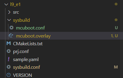
The folder structure should now look like this:
2.3 Next, we will enable logging for MCUboot. For this, we both need to enable logs and set the log level:
Copy
CONFIG_LOG=yCONFIG_MCUBOOT_LOG_LEVEL_INF=y
Kconfig
2.4 Create mcuboot.overlay file in the sysbuild directory.
Now the structure should look like this
2.5 configure mcuboot to start from the proper partition by adding:
After this, we can build and run the sample to see it run with MCUboot. Observe logs from nRF Serial Terminal:
*** Booting MCUboot v2.1.0-dev-12e5ee106034 ****** Using nRF Connect SDK ****** Using Zephyr OS v3.7.99-1f8f3dc29142 ***I: Starting bootloaderI: Bootloader chainload address offset: 0xc000*** Booting My Application v0.0.0 - unknown commit ****** Using nRF Connect SDK v2.9.0-7787b2649840 ****** Using Zephyr OS v3.7.99-1f8f3dc29142 ***
Terminal
Important
On the nRF7002 DK only, ensure that the SPI NOR driver is disabled by default by adding the following lines in sysbuild/mcuboot.conf
CONFIG_SPI=n
CONFIG_SPI_NOR=n
Now, we have MCUboot running before the application. However, we can not yet update the application.
3. Add DFU over UART to MCUboot.
Next, we will add DFU over UART to MCUboot, also known as Serial Recovery. MCUboot configuration options can be found here, and MCUboot Kconfig options specific for Serial Recovery are found here.
3.1 To enable Serial Recovery, we must set CONFIG_MCUBOOT_SERIAL and to enable transport over UART, we must set BOOT_SERIAL_UART. Since these are both for the MCUboot child image, we must set them in mcuboot.conf.
Copy
CONFIG_MCUBOOT_SERIAL=yCONFIG_BOOT_SERIAL_UART=y
Kconfig
Important
For the nRF54LM20 DK it is needed to increase the maximum number of image sectors MCUboot can handle by setting in the mcuboot.conf: CONFIG_BOOT_MAX_IMG_SECTORS_AUTO=n and CONFIG_BOOT_MAX_IMG_SECTORS=256
3.2 Since we now use UART for Serial Recovery, we must disable UART from the console from MCUboot, so this does not try to use the UART at the same time.
Copy
CONFIG_UART_CONSOLE=n
Kconfig
3.3 To indicate that MCUboot is in Serial Recovery mode, it is nice to have an indicator LED. We can enable this by setting CONFIG_MCUBOOT_INDICATION_LED.
Copy
CONFIG_MCUBOOT_INDICATION_LED=y
Kconfig
3.4 We will set which button and LED will be used before testing.
Add the following comment to mcuboot.overlay:
Copy
/* Step 3.4 - Configure button and LED for Serial Recovery */
Note that the alias button1 represents the physical Button 2 on the DK (all Nordic DKs, except nRF54L Series DK). led1 alias represents the physical LED2 on the DK. Aliases and node identifiers in devicetree start from 0, while on the physical board, they start from 1.
Note
On the nRF54L Series DK, the aliases button1 and led1 actually refer to Button 1 and LED1. Since the PCB labels on that DK start from 0.
4. Test Serial Recovery
4.1 Build and flash the application. When you start the kit normally, you see LED1 blink as normal (main).
4.2 Now, hold button 2 (button 1 on the nRF54L15 DK) while resetting the Development Kit. Instead of starting normally, the kit will now enter Serial Recovery mode. You can see this from LED2 (LED1 on the nRF54L15 DK), which should be on.
4.3 While in serial recovery mode, we can use AuTem to communicate with the DK. Navigate to the MCUmgr tag. Here you can see SMP command Groups in the left vertical tabs. Click “Connect” to Connect to the DK. You should see the UART port number and settings printed in the bottom bar:
4.4 With this configuration, we can test listing current images on the DK. Click Images -> Get -> Go to list images:
4.5 Change something in the application to verify that the new firmware image has been flashed.
Before we try to upload a new firmware image to the DK, we should change something in the application, so we can verify that the new firmware image has been flashed. This can, for example be to change the delay in the blinky code. For example, change SLEEP_TIME_MS in main.c from 1000 to 100, then rebuild the code. Do not flash it using the Debugger.
4.5 Upload the new image firmware to the DK.
Now we can upload the new image firmware to the DK, using the Upload tab. From Update files, we see that we can use build/l9_e1/zephyr/zephyr.signed.bin, which is the signed image Sysbuild has automatically generated for us.
Use the “No action”. Since Serial Recovery does not use Swap, we do not need to use “Test” or “Confirm”.
4.6 After the successful upload, reset the DK to see the new image in effect. The video above also shows how to reset the DK over SMP, but you can also use the reset button if you want.
DFU over UART from the application
5. Add DFU over UART to the application.
Next up, we will add DFU over UART to the application. This method uses the mcumgr library.
5.1 First, we must go back to dual slots, as DFU from the application must have two slots. Change SB_CONFIG_MCUBOOT_MODE_SINGLE_APP from y to n in sysbuild.conf. Or simply comment out the line, as the default mode is dual slot.
Copy
SB_CONFIG_MCUBOOT_MODE_SINGLE_APP=n
Kconfig
5.2 Then we add mcumgr configurations and dependencies to the application configuration file (prj.conf). We can take inspiration from the SMP Server sample to find which configurations we need.
For this exercise, we can use the following Kconfigs in prj.conf
Copy
# STEP 5.2 - Enable mcumgr DFU in application# Enable MCUMGR CONFIG_MCUMGR=y# Enable MCUMGR management for both OS and ImagesCONFIG_MCUMGR_GRP_OS=yCONFIG_MCUMGR_GRP_IMG=y# Configure MCUMGR transport to UARTCONFIG_MCUMGR_TRANSPORT_UART=y# Dependencies# Configure dependencies for CONFIG_MCUMGR CONFIG_NET_BUF=yCONFIG_ZCBOR=yCONFIG_CRC=y# Configure dependencies for CONFIG_MCUMGR_GRP_IMG CONFIG_FLASH=yCONFIG_IMG_MANAGER=y# Configure dependencies for CONFIG_IMG_MANAGER CONFIG_STREAM_FLASH=yCONFIG_FLASH_MAP=y# Configure dependencies for CONFIG_MCUMGR_TRANSPORT_UART CONFIG_BASE64=y
Kconfig
5.3 Build and flash the application to the DK.
With this, we can do DFU over UART without entering bootloader mode manually.
Build, flash, and start the DK normally (do not hold any buttons). Now, we can use AuTerm to list images, as before:
Then we change the application code again. Also, increment VERSION_MINOR in the VERSION file. We will be able to see the version in AuTerm.
Copy
VERSION_MAJOR=0# STEP 5.3 - Increment minor versionVERSION_MINOR=1PATCHLEVEL=0VERSION_TWEAK=0EXTRAVERSION=
Pristine build the code (Do not flash using the Debugging) and upload the new firmware image using AuTerm.
The “image number” that you can choose here should stay at 0. If you got another pair of the slots, the next pair would be image 1, and so on. An example of this will be when we update the network core on the nRF5340, which we will see in a later exercise.
Select “Test” to tag the image as “test” after the upload:
5.4 Since we now use a dual slot configuration, an image tagged as “test” will initiate a swapon next reboot. Check Slot 1 in the image list in AuTerm.
Then reboot the DK.
The images will be swapped. We can check this by listing images again.
Now, we can confirm the image by setting the state. This will prevent the image from swapping back on next reset.
Optional: If you have not confirmed, the image swaps back to the old firmware on reset. DFU again with minor version 2 and do not confirm to test this.
Note
To restore the default DK debugger (Interface MCU) behavior with a virtual mass storage disk enabled, use the following J-Link command: MSDEnable. This command can be executed via J-Link Commander (on Windows) or JLinkExe (on Linux).
nRF5340 update
The application core of the nRF5340 can be updated, as explained above.
When doing DFU from the application, no extra configurations are needed to update the network core. Another DFU package file must be used for the network core. Instead of zephyr.signed.bin, use signed_by_mcuboot_and_b0_ipc_radio.bin.
This course does not cover how to use Serial Recovery to update the network core.
Nordic Developer Academy Privacy Policy
1. IntroductionÂ
In this Privacy Policy you will find information on Nordic Semiconductor ASA (“Nordic Semiconductorâ€) processes your personal data when you use the Nordic Developer Academy.
References to “we†and “us†in this document refers to Nordic Semiconductor.
2. Our processing of personal data when you use the Nordic Developer AcademyÂ
2.1 Nordic Developer AcademyÂ
Nordic Semiconductor processes personal data in order to provide you with the features and functionality of the Nordic Developer Academy. Creating a user account is optional, but required if you want to track you progress and view your completed courses and obtained certificates. If you choose to create a user account, we will process the following categories of personal data:
Email
Name
Password (encrypted)
Course progression (e.g. which course you have completely or partly completed)
Certificate information, which consists of name of completed course and the validity of the certificate
Course results
During your use of the Nordic Developer Academy, you may also be asked if you want to provide feedback. If you choose to respond to any such surveys, we will also process the personal data in your responses in that survey.
The legal basis for this processing is GDPR article 6 (1) b. The processing is necessary for Nordic Semiconductor to provide the Nordic Developer Academy under the Terms of Service.
2.2 AnalyticsÂ
If you consent to analytics, Nordic Semiconductor will use Google Analytics to obtain statistics about how the Nordic Developer Academy is used. This includes collecting information on for example what pages are viewed, the duration of the visit, the way in which the pages are maneuvered, what links are clicked, technical information about your equipment. The information is used to learn how Nordic Developer Academy is used and how the user experience can be further developed.
2.2 NewsletterÂ
You can consent to receive newsletters from Nordic from within the Nordic Developer Academy. How your personal data is processed when you sign up for our newsletters is described in the Nordic Semiconductor Privacy Policy.
3. Retention periodÂ
We will store your personal data for as long you use the Nordic Developer Academy. If our systems register that you have not used your account for 36 months, your account will be deleted.
4. Additional informationÂ
Additional information on how we process personal data can be found in the Nordic Semiconductor Privacy Policy and Cookie Policy.
â€â€Â
Nordic Developer Academy Terms of Service
1. Introduction
â€These terms and conditions (“Terms of Useâ€) apply to the use of the Nordic Developer Academy, provided by Nordic Semiconductor ASA, org. nr. 966 011 726, a public limited liability company registered in Norway (“Nordic Semiconductorâ€). â€
Nordic Developer Academy allows the user to take technical courses related to Nordic Semiconductor products, software and services, and obtain a certificate certifying completion of these courses. By completing the registration process for the Nordic Developer Academy, you are agreeing to be bound by these Terms of Use.
These Terms of Use are applicable as long as you have a user account giving you access to Nordic Developer Academy.â€
â€2. Access to and use of Nordic Developer Academy
â€â€Upon acceptance of these Terms of Use you are granted a non-exclusive right of access to, and use of Nordic Developer Academy, as it is provided to you at any time. Nordic Semiconductor provides Nordic Developer Academy to you free of charge, subject to the provisions of these Terms of Use and the Nordic Developer Academy Privacy Policy.
To access select features of Nordic Developer Academy, you need to create a user account. You are solely responsible for the security associated with your user account, including always keeping your login details safe.
You will able to receive an electronic certificate from Nordic Developer Academy upon completion of courses. By issuing you such a certificate, Nordic Semiconductor certifies that you have completed the applicable course, but does not provide any further warrants or endorsements for any particular skills or professional qualifications.
Nordic Semiconductor will continuously develop Nordic Developer Academy with new features and functionality, but reserves the right to remove or alter any existing functions without notice.
â€3. Acceptable use
You undertake that you will use Nordic Developer Academy in accordance with applicable law and regulations, and in accordance with these Terms of Use.†You must not modify, adapt, or hack Nordic Developer Academy or modify another website so as to falsely imply that it is associated with Nordic Developer Academy, Nordic Semiconductor, or any other Nordic Semiconductor product, software or service.
You agree not to reproduce, duplicate, copy, sell, resell or in any other way exploit any portion of Nordic Developer Academy, use of Nordic Developer Academy, or access to Nordic Developer Academy without the express written permission by Nordic Semiconductor. You must not upload, post, host, or transmit unsolicited email, SMS, or \”spam\” messages.
You are responsible for ensuring that the information you post and the content you share does not;
contain false, misleading or otherwise erroneous information
infringe someone else’s copyrights or other intellectual property rights
contain sensitive personal data or
contain information that might be received as offensive or insulting.
Such information may be removed without prior notice.
â€Nordic Semiconductor reserves the right to at any time determine whether a use of Nordic Developer Academy is in violation of its requirements for acceptable use.
Violation of the at any time applicable requirements for acceptable use may result in termination of your account. We will take reasonable steps to notify you and state the reason for termination in such cases.
â€4. Routines for planned maintenance
â€Certain types of maintenance may imply a stop or reduction in availability of Nordic Developer Academy. Nordic Semiconductor does not warrant any level of service availability but will provide its best effort to limit the impact of any planned maintenance on the availability of Nordic Developer Academy.
5. Intellectual property rights
â€Nordic Semiconductor retains all rights to all elements of Nordic Developer Academy. This includes, but is not limited to, the concept, design, trademarks, know-how, trade secrets, copyrights and all other intellectual property rights.
Nordic Semiconductor receives all rights to all content uploaded or created in Nordic Developer Academy. You do not receive any license or usage rights to Nordic Developer Academy beyond what is explicitly stated in this Agreement.
â€6. Liability and damages
â€Nothing within these Terms of Use is intended to limit your statutory data privacy rights as a data subject, as described in the Nordic Developer Academy Privacy Policy. â€You acknowledge that errors might occur from time to time and waive any right to claim for compensation as a result of errors in Nordic Developer Academy. When an error occurs, you shall notify Nordic Semiconductor of the error and provide a description of the error situation.
You agree to indemnify Nordic Semiconductor for any loss, including indirect loss, arising out of or in connection with your use of Nordic Developer Academy or violations of these Terms of Use. â€Nordic Semiconductor shall not be held liable for, and does not warrant that (i) Nordic Developer Academy will meet your specific requirements, (ii) Nordic Developer Academy will be uninterrupted, timely, secure, or error-free, (iii) the results that may be obtained from the use of Nordic Developer Academy will be accurate or reliable, (iv) the quality of any products, services, information, or other material purchased or obtained by you through Nordic Developer Academy will meet your expectations, or that (v) any errors in Nordic Developer Academy will be corrected.
You accept that this is a service provided to you without any payment and hence you accept that Nordic Semiconductor will not be held responsible, or liable, for any breaches of these Terms of Use or any loss connected to your use of Nordic Developer Academy. Unless otherwise follows from mandatory law, Nordic Semiconductor will not accept any such responsibility or liability.
â€7. Change of terms
â€Nordic Semiconductor may update and change the Terms of Use from time to time. Nordic Semiconductor will seek to notify you about significant changes before such changes come into force and give you a possibility to evaluate the effects of proposed changes. Continued use of Nordic Developer Academy after any such changes shall constitute your acceptance of such changes. You can review the current version of the Terms of Use at any time at https://academy.nordicsemi.com/terms-of-service/
â€8. Transfer of rights
â€Nordic Semiconductor is entitled to transfer its rights and obligation pursuant to these Terms of Use to a third party as part of a merger or acquisition process, or as a result of other organizational changes.
â€9. Third Party Services
â€â€To the extent Nordic Developer Academy facilitates access to services provided by a third party, you agree to comply with the terms governing such third party services. Nordic Semiconductor shall not be held liable for any errors, omissions, inaccuracies, etc. related to such third party services.
â€10. Dispute resolution
â€â€The Terms of Use and any other legally binding agreement between yourself and Nordic Semiconductor shall be subject to Norwegian law and Norwegian courts’ exclusive jurisdiction.
Switch language?
Progress is tracked separately for each language. Switching will continue from your progress in that language or start fresh if you haven't begun.
Your current progress is saved, and you can switch back anytime.
•This release includes Long-Term Support (LTS) for five years.
•Patch (minor) releases will address security vulnerabilities and critical bug fixes.
•API stability is guaranteed; breaking changes are only introduced when required by a security fix.
•Notifications for critical bug fixes and security updates via the myNordic notification system (mynordic.nordicsemi.com)
General updates
•Support for nRF54LS05 DK (Available through the early access sampling program) •Support for the nRF54LM20B with Axon NPU for Edge AI applications
Bluetooth LE updates
•Quality of Service module is now production-ready. •New experimental features for RF testing (Direct Test Mode) and low-latency packet handling (LE Flushable ACL).
MCUboot & Partition Manager
•Single-Slot DFU and RAM Load mode are both promoted to fully supported •Partition Manager is officially deprecated in favor of Zephyr's devicetree-based partitioning.