In this exercise, we will learn how to do DFU over Bluetooth Low Energy. This is often known as Firmware Over The Air (FOTA). We will base the exercise on the Bluetooth: Peripheral LBS sample. First, we will enable MCUboot and FOTA in our sample. Then, we will go through how to update the device from a mobile phone.
Documentation on enabling FOTA for each of our products can be seen under Device configuration guides, for example, developing with nRF52 Series and FOTA over Bluetooth Low Energy.
For this exercise, you can use any development kit that supports Bluetooth LE.
nRF91XX DKs
nRF528XX DK
nRF5340 DK
nRF54L Series DK
nRF52 DK
nRF7002 DK
Bluetooth LE
❌
✅
✅
✅
✅
✅
Exercise steps
Open the code base of the exercise by navigating to Create a new application in the nRF Connect for VS Code extension, select Copy a sample, and search for Lesson 9 – Exercise 5.
For the nRF54LM20 DK, ensure that you increase the sectors by setting CONFIG_BOOT_MAX_IMG_SECTORS=256 in mcuboot.conf
2.2: Enable FOTA in the application; Set this in prj.conf:
Copy
# STEP 2.2 - Enable FOTA over Bluetooth LECONFIG_NCS_SAMPLE_MCUMGR_BT_OTA_DFU=y
Kconfig
This option will automatically add a service for FOTA to Bluetooth LE if you have already set up Bluetooth LE. That means that the application still has to start Bluetooth LE, so while this option works for Bluetooth samples out of the box, it will not enable FOTA automatically for non-Bluetooth projects.
In Zephyr, a proper configuration is needed to enable FOTA. An example of how to set this up can be seen in the SMP Server sample. However, the nRF Connect SDK includes the option CONFIG_NCS_SAMPLE_MCUMGR_BT_OTA_DFU, which configures the project for us. This option makes it easier for us to enable FOTA, so we will use that.
Note
In the nRF Connect SDK, there are many options prefixed with CONFIG_NCS_SAMPLE. These options are used to preconfigure projects and can include Zephyr subset Kconfig options and source code variants. Although this significantly helps with project configuration, it is most suitable for prototyping and learning phases.
For your custom production project, we recommend that you look at what option CONFIG_NCS_SAMPLE_MCUMGR_BT_OTA_DFU sets for you, and include the ones from there you need instead.
Copy
configNCS_SAMPLE_MCUMGR_BT_OTA_DFUbool"MCUmgr OTA DFU over Bluetooth"selectMCUMGRselectNET_BUFselectZCBORselectCRCselectMCUMGR_TRANSPORT_BTimplyMCUMGR_TRANSPORT_BT_CONN_PARAM_CONTROLimplyIMG_MANAGERimplySTREAM_FLASHimplyFLASH_MAPimplyFLASHimplyMCUMGR_GRP_IMGimplyMCUMGR_GRP_OSimplyMCUMGR_GRP_OS_BOOTLOADER_INFOimplyMCUMGR_TRANSPORT_BT_REASSEMBLYimplyNCS_SAMPLE_MCUMGR_BT_OTA_DFU_SPEEDUPdependsonBT_PERIPHERALdependsonBOOTLOADER_MCUBOOT
Kconfig
Also, it’s highly recommended to authenticate and encrypt the connection where the DFU will take place. This can be done by enabling CONFIG_MCUMGR_TRANSPORT_BT_PERM_RW_AUTHEN. When this option is enabled, a 6-digit passkey will be displayed on your serial terminal, which must be entered into the phone app.
Passkey for XX:XX:XX:XX:XX:XX (random): XXXXXX
Terminal
3. Build and flash the application.
4. Build a new image.
4.1 Next, create a new image with noticeable changes. Change the LED blinking period in main.c (e.g. from 1000 ms to 200 ms) and the project version (to 3.0.0) in the VERSION file, then build the project again.
DO NOT flash it using the debugger. Instead, we will send the zephyr.signed.bin file found in the build/l9_e5/zephyr/ folder to your mobile device in a later step. You can alternatively use the dfu_application.zip file found in the build/ folder.
5. Update the firmware using nRF Connect Device Manager.
5.1 Install the nRF Connect Device Manager app on your mobile device.
To perform DFU, we will use the nRF Connect Device Manager app for mobile (Android and iOS). Install this on your phone.
Another alternative for Android and iOS is to use the nRF Connect for Mobile. For PC, you can use AuTerm.
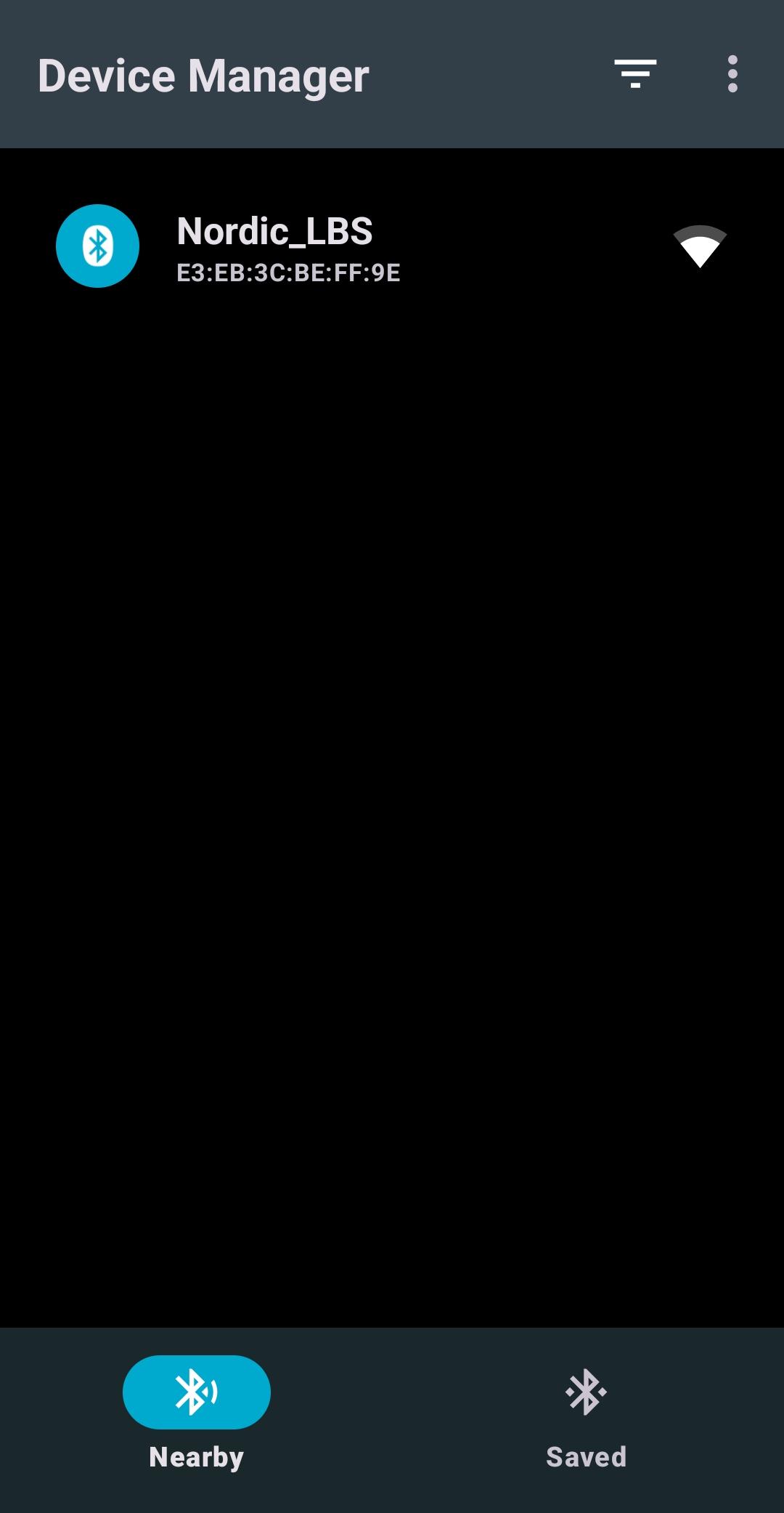
5.2 Open the Device Manager app. It will first open the Scan tab, where nearby Bluetooth LE advertising devices are displayed, including the “Nordic_LBS” device. If you don’t see it, open the filter settings menu (the three-line sliders icon) and adjust the filter as needed.
When developing your own mobile app, you’ll likely filter by your device’s UUID rather than a generic name or SMP UUID. This means the advertising device must include that UUID in its advertising packets or scan response, as covered in Bluetooth Low Energy Fundamentals on Advertising.
nRF Connect Device Manager Mobile app – Android version
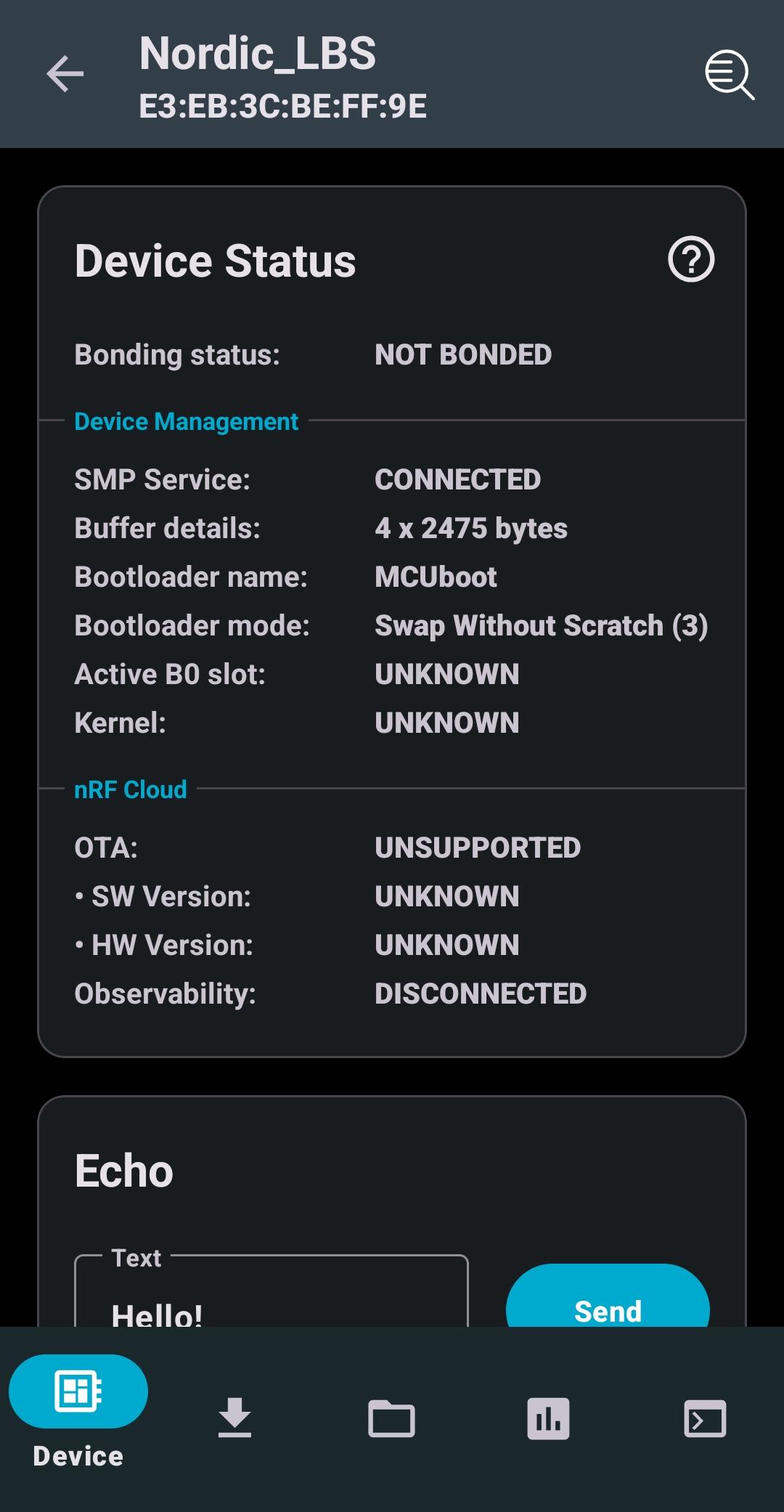
5.3 Select the Nordic_LBS to connect to.
Observe the features listed in the menubar at the bottom. These are SMP Services. The first one to be displayed is the Device tab. This tab should look like the screenshot below.
This tab displays bonding state, SMP (Simple Management Protocol) service connection and buffer details, bootloader info (name, mode, active slot), kernel status, and nRF Cloud-related fields like OTA support, SW/HW version, and observability connection state, essentially a snapshot of the connected device’s management and update-related metadata.
nRF Connect Device Manager Mobile app – Android version – Device tab
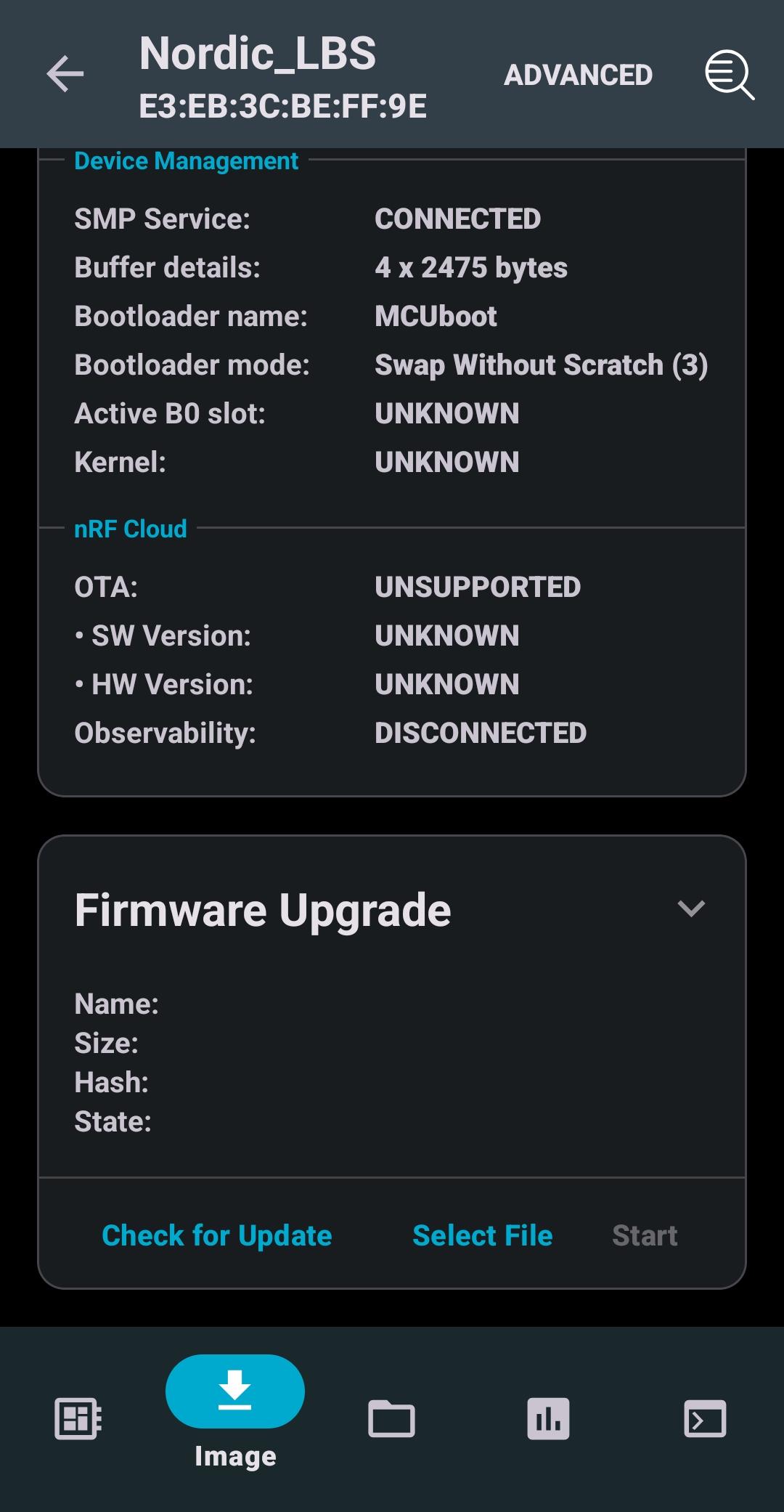
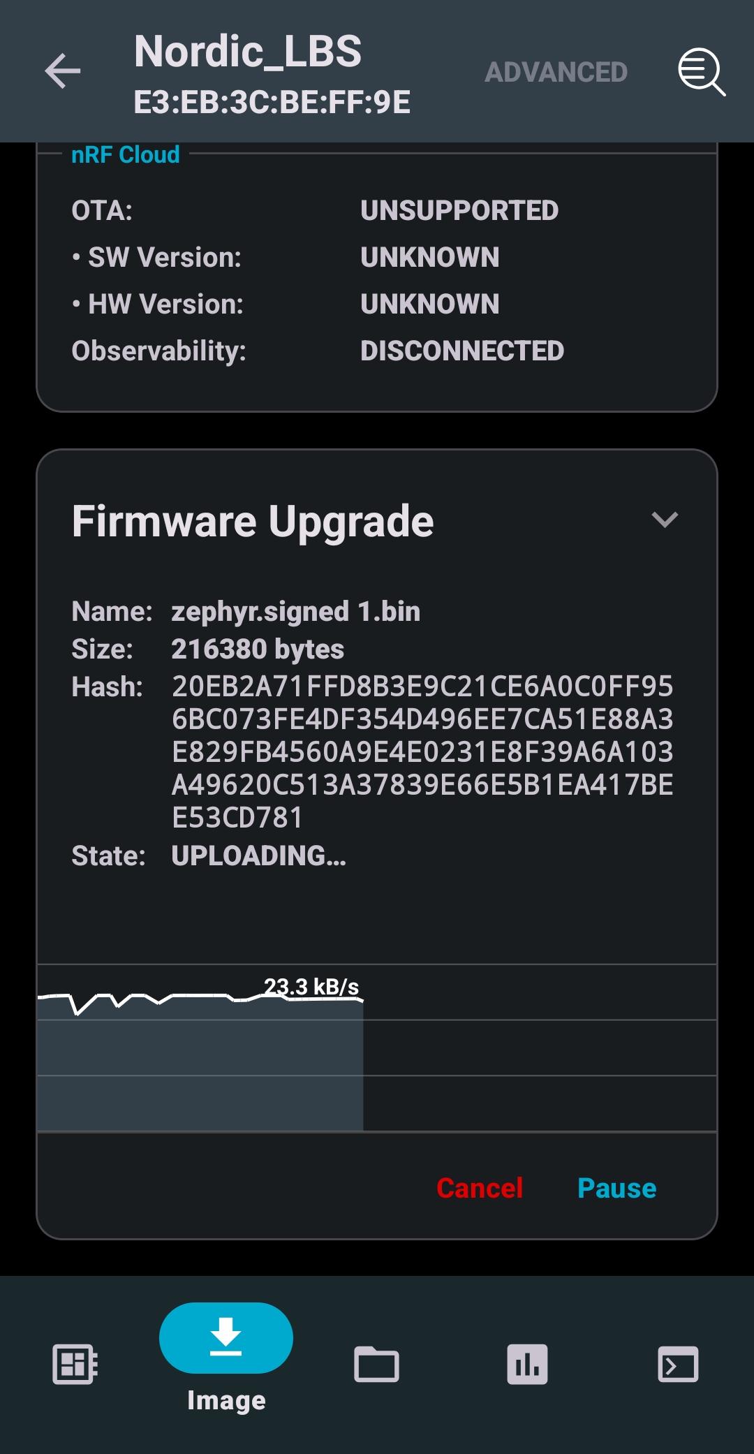
Open the Image tab, which we will use to send a new firmware image to the device.
nRF Connect Device Manager Mobile app – Android version – Image tab
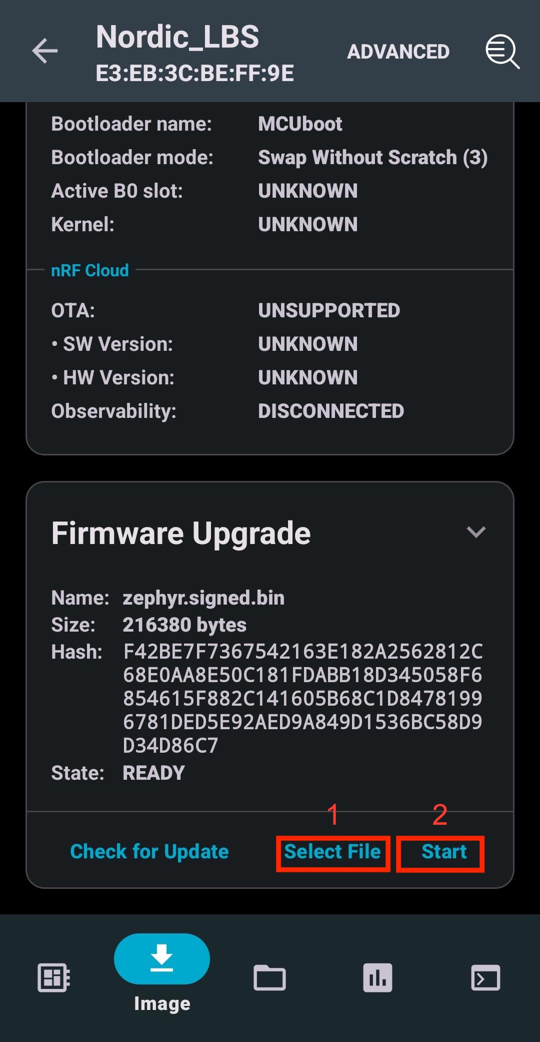
5.4 The first step is to move our new firmware image to the phone. This would be the same file used in the previous exercises: build/l9_e5/zephyr/zephyr.signed.bin. Use your preferred method to transfer this file from your computer to the phone.
5.5 Click “Select file” and choose zephyr_signed.bin, and then press “Start”. You learned about “Test” and “Confirm” previously in this course. The “Test & Confirm” option first tags the image with “test”, and after the swap, the app will reconnect to the chip and confirm the image before it reverts. It is up to you which choice you use here.
More on this
For more FOTA options, tap the Advanced button at the top of the screen. You can also store firmware updates in nRF Cloud and have the mobile app check nRF Cloud for new updates.
Now, you can observe the process of transferring the file into the device (in this case, nRF54L15 DK is used).
Important
The transfer speed is greatly influenced by the central mobile device and its operating system (Android or iOS). Additionally, the speed varies between different System on Chip (SoC) series. For instance, the nRF54L Series has twice the processing power of the nRF52 Series.
When the process is completed, the device will restart, and you can see new LED behavior. We can also check the version of the new image as done in the next step through the ADVANCED option.
5.6 After the device is reset, open it again. Head to Image tab, press ADVANCED from the top, and press read to see that the current version matches the one we set in Step 4.
Optional: Simultaneous updates for both cores of the nRF5340
The above exercise will work for the nRF5340 to update only the application core. However, as we learned from the theory on nRF5340 DFU, we often want to update both cores at the same time. This is referred to as simultaneous FOTA, which is covered in-depth as a separate optional exercise: Simultaneous updates for both cores of the nRF5340.
Nordic Developer Academy Privacy Policy
1. Introduction
In this Privacy Policy you will find information on Nordic Semiconductor ASA (“Nordic Semiconductor”) processes your personal data when you use the Nordic Developer Academy.
References to “we” and “us” in this document refers to Nordic Semiconductor.
2. Our processing of personal data when you use the Nordic Developer Academy
2.1 Nordic Developer Academy
Nordic Semiconductor processes personal data in order to provide you with the features and functionality of the Nordic Developer Academy. Creating a user account is optional, but required if you want to track you progress and view your completed courses and obtained certificates. If you choose to create a user account, we will process the following categories of personal data:
Email
Name
Password (encrypted)
Course progression (e.g. which course you have completely or partly completed)
Certificate information, which consists of name of completed course and the validity of the certificate
Course results
During your use of the Nordic Developer Academy, you may also be asked if you want to provide feedback. If you choose to respond to any such surveys, we will also process the personal data in your responses in that survey.
The legal basis for this processing is GDPR article 6 (1) b. The processing is necessary for Nordic Semiconductor to provide the Nordic Developer Academy under the Terms of Service.
2.2 Analytics
If you consent to analytics, Nordic Semiconductor will use Google Analytics to obtain statistics about how the Nordic Developer Academy is used. This includes collecting information on for example what pages are viewed, the duration of the visit, the way in which the pages are maneuvered, what links are clicked, technical information about your equipment. The information is used to learn how Nordic Developer Academy is used and how the user experience can be further developed.
2.2 Newsletter
You can consent to receive newsletters from Nordic from within the Nordic Developer Academy. How your personal data is processed when you sign up for our newsletters is described in the Nordic Semiconductor Privacy Policy.
3. Retention period
We will store your personal data for as long you use the Nordic Developer Academy. If our systems register that you have not used your account for 36 months, your account will be deleted.
4. Additional information
Additional information on how we process personal data can be found in the Nordic Semiconductor Privacy Policy and Cookie Policy.
Nordic Developer Academy Terms of Service
1. Introduction
These terms and conditions (“Terms of Use”) apply to the use of the Nordic Developer Academy, provided by Nordic Semiconductor ASA, org. nr. 966 011 726, a public limited liability company registered in Norway (“Nordic Semiconductor”).
Nordic Developer Academy allows the user to take technical courses related to Nordic Semiconductor products, software and services, and obtain a certificate certifying completion of these courses. By completing the registration process for the Nordic Developer Academy, you are agreeing to be bound by these Terms of Use.
These Terms of Use are applicable as long as you have a user account giving you access to Nordic Developer Academy.
2. Access to and use of Nordic Developer Academy
Upon acceptance of these Terms of Use you are granted a non-exclusive right of access to, and use of Nordic Developer Academy, as it is provided to you at any time. Nordic Semiconductor provides Nordic Developer Academy to you free of charge, subject to the provisions of these Terms of Use and the Nordic Developer Academy Privacy Policy.
To access select features of Nordic Developer Academy, you need to create a user account. You are solely responsible for the security associated with your user account, including always keeping your login details safe.
You will able to receive an electronic certificate from Nordic Developer Academy upon completion of courses. By issuing you such a certificate, Nordic Semiconductor certifies that you have completed the applicable course, but does not provide any further warrants or endorsements for any particular skills or professional qualifications.
Nordic Semiconductor will continuously develop Nordic Developer Academy with new features and functionality, but reserves the right to remove or alter any existing functions without notice.
3. Acceptable use
You undertake that you will use Nordic Developer Academy in accordance with applicable law and regulations, and in accordance with these Terms of Use. You must not modify, adapt, or hack Nordic Developer Academy or modify another website so as to falsely imply that it is associated with Nordic Developer Academy, Nordic Semiconductor, or any other Nordic Semiconductor product, software or service.
You agree not to reproduce, duplicate, copy, sell, resell or in any other way exploit any portion of Nordic Developer Academy, use of Nordic Developer Academy, or access to Nordic Developer Academy without the express written permission by Nordic Semiconductor. You must not upload, post, host, or transmit unsolicited email, SMS, or \”spam\” messages.
You are responsible for ensuring that the information you post and the content you share does not;
contain false, misleading or otherwise erroneous information
infringe someone else’s copyrights or other intellectual property rights
contain sensitive personal data or
contain information that might be received as offensive or insulting.
Such information may be removed without prior notice.
Nordic Semiconductor reserves the right to at any time determine whether a use of Nordic Developer Academy is in violation of its requirements for acceptable use.
Violation of the at any time applicable requirements for acceptable use may result in termination of your account. We will take reasonable steps to notify you and state the reason for termination in such cases.
4. Routines for planned maintenance
Certain types of maintenance may imply a stop or reduction in availability of Nordic Developer Academy. Nordic Semiconductor does not warrant any level of service availability but will provide its best effort to limit the impact of any planned maintenance on the availability of Nordic Developer Academy.
5. Intellectual property rights
Nordic Semiconductor retains all rights to all elements of Nordic Developer Academy. This includes, but is not limited to, the concept, design, trademarks, know-how, trade secrets, copyrights and all other intellectual property rights.
Nordic Semiconductor receives all rights to all content uploaded or created in Nordic Developer Academy. You do not receive any license or usage rights to Nordic Developer Academy beyond what is explicitly stated in this Agreement.
6. Liability and damages
Nothing within these Terms of Use is intended to limit your statutory data privacy rights as a data subject, as described in the Nordic Developer Academy Privacy Policy. You acknowledge that errors might occur from time to time and waive any right to claim for compensation as a result of errors in Nordic Developer Academy. When an error occurs, you shall notify Nordic Semiconductor of the error and provide a description of the error situation.
You agree to indemnify Nordic Semiconductor for any loss, including indirect loss, arising out of or in connection with your use of Nordic Developer Academy or violations of these Terms of Use. Nordic Semiconductor shall not be held liable for, and does not warrant that (i) Nordic Developer Academy will meet your specific requirements, (ii) Nordic Developer Academy will be uninterrupted, timely, secure, or error-free, (iii) the results that may be obtained from the use of Nordic Developer Academy will be accurate or reliable, (iv) the quality of any products, services, information, or other material purchased or obtained by you through Nordic Developer Academy will meet your expectations, or that (v) any errors in Nordic Developer Academy will be corrected.
You accept that this is a service provided to you without any payment and hence you accept that Nordic Semiconductor will not be held responsible, or liable, for any breaches of these Terms of Use or any loss connected to your use of Nordic Developer Academy. Unless otherwise follows from mandatory law, Nordic Semiconductor will not accept any such responsibility or liability.
7. Change of terms
Nordic Semiconductor may update and change the Terms of Use from time to time. Nordic Semiconductor will seek to notify you about significant changes before such changes come into force and give you a possibility to evaluate the effects of proposed changes. Continued use of Nordic Developer Academy after any such changes shall constitute your acceptance of such changes. You can review the current version of the Terms of Use at any time at https://academy.nordicsemi.com/terms-of-service/
8. Transfer of rights
Nordic Semiconductor is entitled to transfer its rights and obligation pursuant to these Terms of Use to a third party as part of a merger or acquisition process, or as a result of other organizational changes.
9. Third Party Services
To the extent Nordic Developer Academy facilitates access to services provided by a third party, you agree to comply with the terms governing such third party services. Nordic Semiconductor shall not be held liable for any errors, omissions, inaccuracies, etc. related to such third party services.
10. Dispute resolution
The Terms of Use and any other legally binding agreement between yourself and Nordic Semiconductor shall be subject to Norwegian law and Norwegian courts’ exclusive jurisdiction.
Switch language?
Progress is tracked separately for each language. Switching will continue from your progress in that language or start fresh if you haven't begun.
Your current progress is saved, and you can switch back anytime.
•This release includes Long-Term Support (LTS) for five years.
•Patch (minor) releases will address security vulnerabilities and critical bug fixes.
•API stability is guaranteed; breaking changes are only introduced when required by a security fix.
•Notifications for critical bug fixes and security updates via the myNordic notification system (mynordic.nordicsemi.com)
General updates
•Support for nRF54LS05 DK (Available through the early access sampling program) •Support for the nRF54LM20B with Axon NPU for Edge AI applications
Bluetooth LE updates
•Quality of Service module is now production-ready. •New experimental features for RF testing (Direct Test Mode) and low-latency packet handling (LE Flushable ACL).
MCUboot & Partition Manager
•Single-Slot DFU and RAM Load mode are both promoted to fully supported •Partition Manager is officially deprecated in favor of Zephyr's devicetree-based partitioning.