Exercise 2 – Connecting to the BH1749 Ambient Light Sensor on the Thingy:91 and Thingy:53
Note
This exercise does not work on the Thingy:91 X, as it does not have the BH1749 Ambient Light Sensor.
Instead of the usual development kits, we have used to run samples and exercises throughout this course, this exercise uses a special type of Nordic Semiconductors’ prototyping boards called the Thingy. This exercise can be run on either a Thingy:53 or a Thingy:91.
Thingy:53
Thingy:91
The Thingy is an easy-to-use battery-operated prototyping board that allows the user to build a proof-of-concept in minimal time as it contains onboard a variety of sensors and interfaces. For this exercise, to illustrate how to use the I2C interface, we will be using either the Thingy:53 or the Thingy:91 and make use of the BH1749: Ambient Light Sensor they have onboard.
Thingy:53 PCB, front view, light sensor location
Thingy:91 PCB, back view, light sensor location
The BH1749NUC is a color sensor which uses I2C for its interface. The Integrated Circuit (IC) onboard the sensor senses Red, Green, Blue (RGB), and infrared colors, then represents their intensities as digital values stored in 2 bytes for each value.
In this exercise, we will read the RGB value from the sensor and print it on a serial terminal.
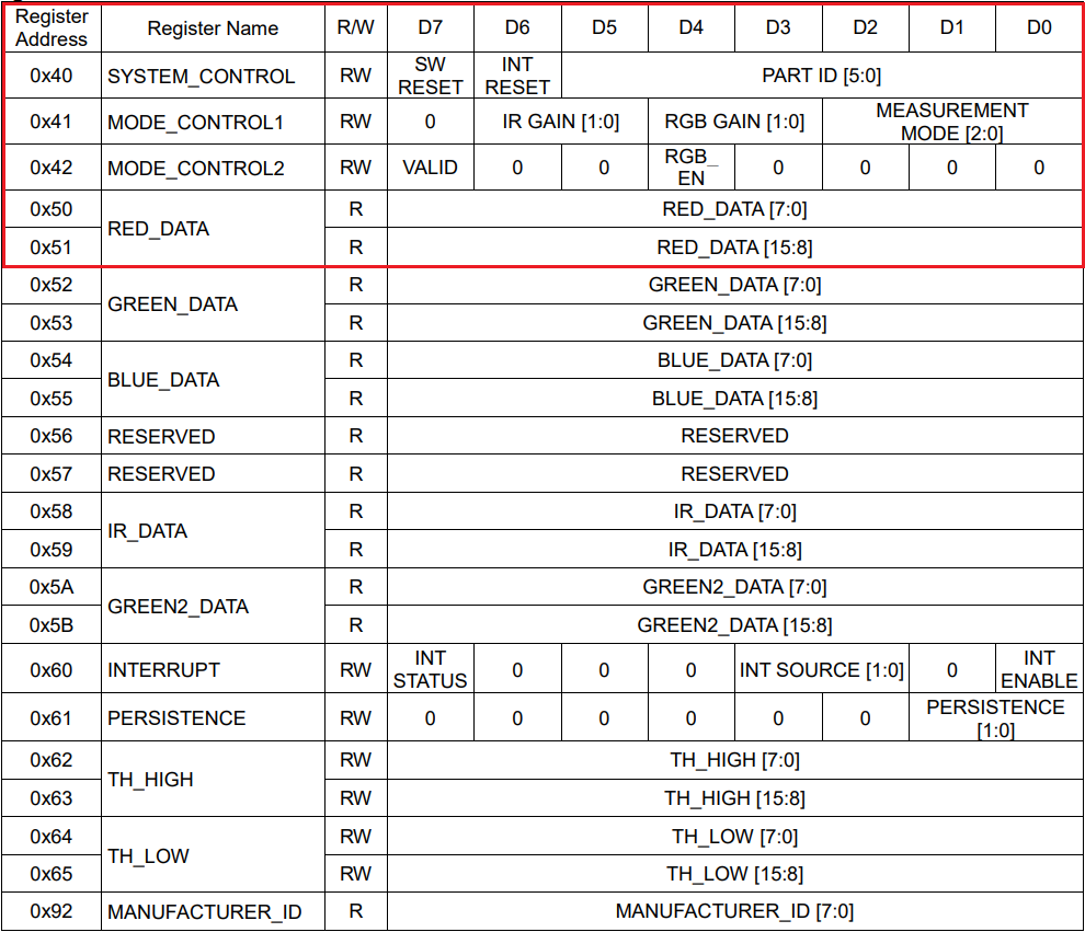
Registers’ table as found in BH1749NUC color sensor datasheet
The above table shows the registers of the color sensor and their corresponding addresses. For our exercise, the relevant registers are the 4 registers in the red box. The 4 registers are, the basic SYSTEM_CONTROL register, the 2 MODE_CONTROL registers, used to set specific modes of the sensor, and lastly the RED_DATA register and more specifically the lower byte [7-0] in it, located at address 0x50.
To read color data (RGB without the IR value) from the sensor, you need to first set up the sensor mode, by writing to the MODE_CONTROL1 register. After that, you will need to enable measurements by writing to the MODE_CONTROL2 register. Lastly, you will need to do the actual reading from the data registers of RED_DATA, GREEN_DATA, and BLUE_DATA. We will do a burst read starting from the first byte of the RED_DATA register.
Note that you can use the sensor’s driver (found here <install_path>\nrf\drivers\sensor\bh1749>) to enable other features as well, such as reading infrared (IR) light intensity and utilizing interrupts. However, this exercise focuses only on the I2C aspect of interfacing the sensor, hence extra features are not within the scope of this exercise.
2. Enable the I2C driver by adding the following line to the prj.conf file.
Copy
CONFIG_I2C=y
Kconfig
Important
If you are building with TF-M (thingyxx/nrfxxxx/ns), you will need to disable logging for TF-M. The UART peripheral used for TF-M shares the same base address as the TWIM peripheral used in this exercise, and it’s enabled by default in nRF Connect SDK 2.6.0 and above. To disable it, simply add these two Kconfig symbols in prj.conf.
CONFIG_TFM_SECURE_UART=n
CONFIG_TFM_LOG_LEVEL_SILENCE=y
3. In main.c , include the header file of the I2C API.
Copy
#include<zephyr/drivers/i2c.h>
C
4. To display the sensor readings on the console, we will use a simple printk().
4.1 Include the header file <sys/printk.h> to use printk()
Copy
#include<zephyr/sys/printk.h>
C
4.2 Enable floating point format specifiers in prj.conf by adding the symbol
Copy
CONFIG_CBPRINTF_FP_SUPPORT=y
Kconfig
5. (No action needed) In the previous exercise, we were using an external expansion board. Since the sensor was on that expansion board, and not built-in on a Nordic Semiconductor board, we needed a step to specify that the sensor is connected to an I2Ccontroller and provide its address in an overlay file.
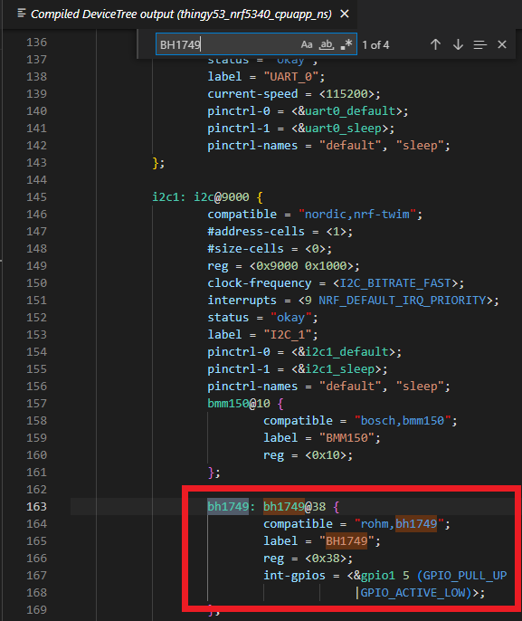
In this exercise, the sensor is built-in on the Thingy board and is already specified in the devicetree file. You can verify this by checking the devicetree file and searching for the BH1749 sensor as shown below.
6. Get the node identifier of the sensor. This was explained in detail in step 4 of the I2C Driver section.
Copy
#define I2C_NODE DT_NODELABEL(bh1749)
C
7. Retrieve the API-specific device structure, make sure that the device is ready to use, and print an error message if the I2C device is not ready to use:
Copy
staticconststruct i2c_dt_spec dev_i2c = I2C_DT_SPEC_GET(I2C_NODE);if (!device_is_ready(dev_i2c.bus)) {printk("I2C bus %s is not ready!\n\r",dev_i2c.bus->name);return -1;}
C
8. Define the addresses of the relevant registers, which can be found in the sensor datasheet. This information typically goes into a separate header file (.h). However, for the sake of keeping this demonstration simple, we will add them in main.c.
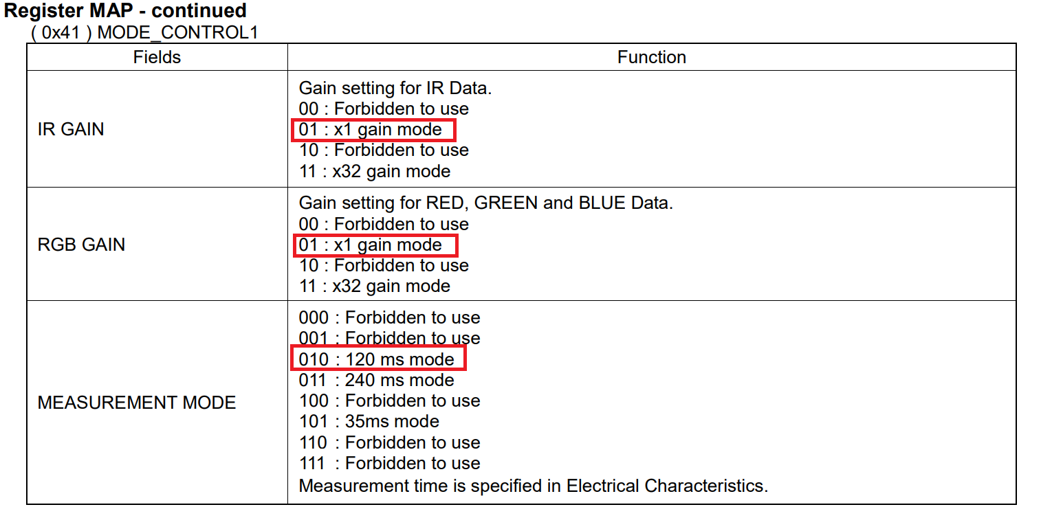
9. Setup the sensor by writing the value 0x2A to the MODE_CONTROL1 register.
As evident by the MODE_CONTROL1 register map below, 0x2A (0 0101010 in binary) would mean:
IR Gain: x1,
RGB Gain: x1
Measurement mode: 120ms
Copy
char buff1[] = {BH1749_MODE_CONTROL1,BH1749_MODE_CONTROL1_DEFAULTS};ret = i2c_write_dt(&dev_i2c,buff1,sizeof(buff1));if(ret != 0){printk("Failed to write to I2C device address 0x%c at Reg. 0x%c\n",dev_i2c.addr,BH1749_MODE_CONTROL1);}
C
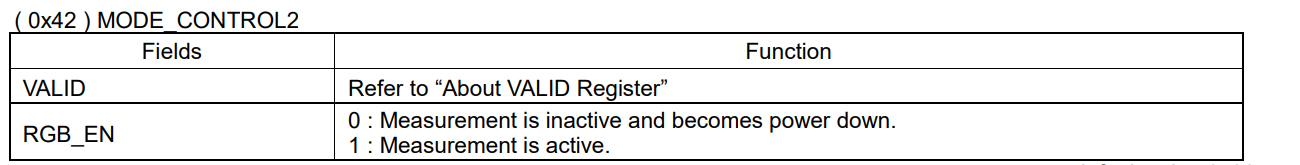
10. To read the RGB values from the sensor we need to enable measurement by writing 1 to bit 4 of the MODE_CONTROL2 register. We will use the i2c_write_dt() API as shown below
Copy
char buff2[] = {BH1749_MODE_CONTROL2,BH1749_MODE_CONTROL2_RGB_EN_ENABLE};ret = i2c_write_dt(&dev_i2c,buff2,sizeof(buff2));if(ret != 0){printk("Failed to write to I2C device address 0x%c at Reg. 0x%c\n",dev_i2c.addr,BH1749_MODE_CONTROL2);}
C
11. Read the RGB values from the RED_DATA, GREEN_DATA, and BLUE_DATA registers.
Since these registers are sequential, we will do a burst read starting from the first byte of the RED_DATA which is at address 0x50 (BH1749_RED_DATA_LSB). Notice that we are reading six bytes (as the size of rgb_value the buffer is 6 bytes) so the register would store the values of RGB as: (most significant bit)BBGGRR(least significant bit)
Copy
uint8_trgb_value[6]= {0};//Do a burst read of 6 bytes as each color channel is 2 bytesret = i2c_burst_read_dt(&dev_i2c, BH1749_RED_DATA_LSB,rgb_value,sizeof(rgb_value));if(ret != 0){printk("Failed to read to I2C device address 0x%c at Reg. 0x%c\n",dev_i2c.addr,BH1749_RED_DATA_LSB); }//Print reading to console printk("_______________________________\n");printk("Red Value:\t%d\n", (rgb_value[0] | rgb_value[1] << 8));printk("Green Value:\t%d\n", (rgb_value[2] | rgb_value[3] << 8));printk("Blue Value:\t%d\n", (rgb_value[4] | rgb_value[5] << 8));
C
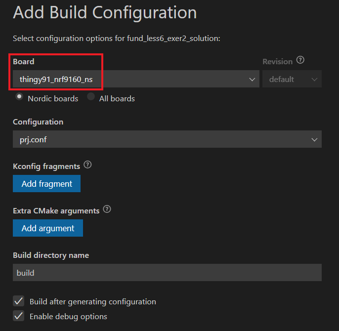
12. Build the application.
To build for a Thingy:91, use the same building procedure as used in the previous exercises and choose thingy91_nrf9160_ns as the target board in the Add Build Configuration window as shown below.
To build for the Thingy:53, use thingy53_nrf5340_cpuapp_ns as the target board instead.
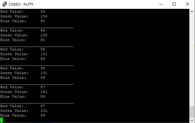
13. Flash the application to your device.
To read more about flashing applications for the Thingy, click here for instructions regarding the Thingy:53 or click here for instructions regarding the Thingy:91. You should see an output similar to the one below.
To verify that the color values respond to ambient light changes, you can try for example covering the light sensor on the board (remember the location of the light sensor varies according to the Thingy version you are using, please refer to the board pictures at the top of this page) and observe how the values drastically decrease. You can also subject the board to a certain light color and observe how this value in the output increases.
The solution for this exercise can be found in the GitHub repository, l6/l6_e2_sol.
Nordic Developer Academy Privacy Policy
1. Introduction
In this Privacy Policy you will find information on Nordic Semiconductor ASA (“Nordic Semiconductor”) processes your personal data when you use the Nordic Developer Academy.
References to “we” and “us” in this document refers to Nordic Semiconductor.
2. Our processing of personal data when you use the Nordic Developer Academy
2.1 Nordic Developer Academy
Nordic Semiconductor processes personal data in order to provide you with the features and functionality of the Nordic Developer Academy. Creating a user account is optional, but required if you want to track you progress and view your completed courses and obtained certificates. If you choose to create a user account, we will process the following categories of personal data:
Email
Name
Password (encrypted)
Course progression (e.g. which course you have completely or partly completed)
Certificate information, which consists of name of completed course and the validity of the certificate
Course results
During your use of the Nordic Developer Academy, you may also be asked if you want to provide feedback. If you choose to respond to any such surveys, we will also process the personal data in your responses in that survey.
The legal basis for this processing is GDPR article 6 (1) b. The processing is necessary for Nordic Semiconductor to provide the Nordic Developer Academy under the Terms of Service.
2.2 Analytics
If you consent to analytics, Nordic Semiconductor will use Google Analytics to obtain statistics about how the Nordic Developer Academy is used. This includes collecting information on for example what pages are viewed, the duration of the visit, the way in which the pages are maneuvered, what links are clicked, technical information about your equipment. The information is used to learn how Nordic Developer Academy is used and how the user experience can be further developed.
2.2 Newsletter
You can consent to receive newsletters from Nordic from within the Nordic Developer Academy. How your personal data is processed when you sign up for our newsletters is described in the Nordic Semiconductor Privacy Policy.
3. Retention period
We will store your personal data for as long you use the Nordic Developer Academy. If our systems register that you have not used your account for 36 months, your account will be deleted.
4. Additional information
Additional information on how we process personal data can be found in the Nordic Semiconductor Privacy Policy and Cookie Policy.
Nordic Developer Academy Terms of Service
1. Introduction
These terms and conditions (“Terms of Use”) apply to the use of the Nordic Developer Academy, provided by Nordic Semiconductor ASA, org. nr. 966 011 726, a public limited liability company registered in Norway (“Nordic Semiconductor”).
Nordic Developer Academy allows the user to take technical courses related to Nordic Semiconductor products, software and services, and obtain a certificate certifying completion of these courses. By completing the registration process for the Nordic Developer Academy, you are agreeing to be bound by these Terms of Use.
These Terms of Use are applicable as long as you have a user account giving you access to Nordic Developer Academy.
2. Access to and use of Nordic Developer Academy
Upon acceptance of these Terms of Use you are granted a non-exclusive right of access to, and use of Nordic Developer Academy, as it is provided to you at any time. Nordic Semiconductor provides Nordic Developer Academy to you free of charge, subject to the provisions of these Terms of Use and the Nordic Developer Academy Privacy Policy.
To access select features of Nordic Developer Academy, you need to create a user account. You are solely responsible for the security associated with your user account, including always keeping your login details safe.
You will able to receive an electronic certificate from Nordic Developer Academy upon completion of courses. By issuing you such a certificate, Nordic Semiconductor certifies that you have completed the applicable course, but does not provide any further warrants or endorsements for any particular skills or professional qualifications.
Nordic Semiconductor will continuously develop Nordic Developer Academy with new features and functionality, but reserves the right to remove or alter any existing functions without notice.
3. Acceptable use
You undertake that you will use Nordic Developer Academy in accordance with applicable law and regulations, and in accordance with these Terms of Use. You must not modify, adapt, or hack Nordic Developer Academy or modify another website so as to falsely imply that it is associated with Nordic Developer Academy, Nordic Semiconductor, or any other Nordic Semiconductor product, software or service.
You agree not to reproduce, duplicate, copy, sell, resell or in any other way exploit any portion of Nordic Developer Academy, use of Nordic Developer Academy, or access to Nordic Developer Academy without the express written permission by Nordic Semiconductor. You must not upload, post, host, or transmit unsolicited email, SMS, or \”spam\” messages.
You are responsible for ensuring that the information you post and the content you share does not;
contain false, misleading or otherwise erroneous information
infringe someone else’s copyrights or other intellectual property rights
contain sensitive personal data or
contain information that might be received as offensive or insulting.
Such information may be removed without prior notice.
Nordic Semiconductor reserves the right to at any time determine whether a use of Nordic Developer Academy is in violation of its requirements for acceptable use.
Violation of the at any time applicable requirements for acceptable use may result in termination of your account. We will take reasonable steps to notify you and state the reason for termination in such cases.
4. Routines for planned maintenance
Certain types of maintenance may imply a stop or reduction in availability of Nordic Developer Academy. Nordic Semiconductor does not warrant any level of service availability but will provide its best effort to limit the impact of any planned maintenance on the availability of Nordic Developer Academy.
5. Intellectual property rights
Nordic Semiconductor retains all rights to all elements of Nordic Developer Academy. This includes, but is not limited to, the concept, design, trademarks, know-how, trade secrets, copyrights and all other intellectual property rights.
Nordic Semiconductor receives all rights to all content uploaded or created in Nordic Developer Academy. You do not receive any license or usage rights to Nordic Developer Academy beyond what is explicitly stated in this Agreement.
6. Liability and damages
Nothing within these Terms of Use is intended to limit your statutory data privacy rights as a data subject, as described in the Nordic Developer Academy Privacy Policy. You acknowledge that errors might occur from time to time and waive any right to claim for compensation as a result of errors in Nordic Developer Academy. When an error occurs, you shall notify Nordic Semiconductor of the error and provide a description of the error situation.
You agree to indemnify Nordic Semiconductor for any loss, including indirect loss, arising out of or in connection with your use of Nordic Developer Academy or violations of these Terms of Use. Nordic Semiconductor shall not be held liable for, and does not warrant that (i) Nordic Developer Academy will meet your specific requirements, (ii) Nordic Developer Academy will be uninterrupted, timely, secure, or error-free, (iii) the results that may be obtained from the use of Nordic Developer Academy will be accurate or reliable, (iv) the quality of any products, services, information, or other material purchased or obtained by you through Nordic Developer Academy will meet your expectations, or that (v) any errors in Nordic Developer Academy will be corrected.
You accept that this is a service provided to you without any payment and hence you accept that Nordic Semiconductor will not be held responsible, or liable, for any breaches of these Terms of Use or any loss connected to your use of Nordic Developer Academy. Unless otherwise follows from mandatory law, Nordic Semiconductor will not accept any such responsibility or liability.
7. Change of terms
Nordic Semiconductor may update and change the Terms of Use from time to time. Nordic Semiconductor will seek to notify you about significant changes before such changes come into force and give you a possibility to evaluate the effects of proposed changes. Continued use of Nordic Developer Academy after any such changes shall constitute your acceptance of such changes. You can review the current version of the Terms of Use at any time at https://academy.nordicsemi.com/terms-of-service/
8. Transfer of rights
Nordic Semiconductor is entitled to transfer its rights and obligation pursuant to these Terms of Use to a third party as part of a merger or acquisition process, or as a result of other organizational changes.
9. Third Party Services
To the extent Nordic Developer Academy facilitates access to services provided by a third party, you agree to comply with the terms governing such third party services. Nordic Semiconductor shall not be held liable for any errors, omissions, inaccuracies, etc. related to such third party services.
10. Dispute resolution
The Terms of Use and any other legally binding agreement between yourself and Nordic Semiconductor shall be subject to Norwegian law and Norwegian courts’ exclusive jurisdiction.
Switch language?
Progress is tracked separately for each language. Switching will continue from your progress in that language or start fresh if you haven't begun.
Your current progress is saved, and you can switch back anytime.
•Support for nRF54LS05 DK (Available through the early access sampling program) •Support for the nRF54LM20B with Axon NPU for Edge AI applications
Bluetooth LE updates
•Quality of Service module is now production-ready. •New experimental features for RF testing (Direct Test Mode) and low-latency packet handling (LE Flushable ACL).
MCUboot & Partition Manager
•Single-Slot DFU and RAM Load mode are both promoted to fully supported •Partition Manager is officially deprecated in favor of Zephyr's devicetree-based partitioning.
General updates
•Added comprehensive support for the nRF54L Series. •Bug fixes and improvements. •Hardware model v1, which was deprecated in nRF Connect SDK 2.7.0, has now been removed. •Multi-image builds functionality (parent-child images), which was deprecated in nRF Connect SDK v2.7.0 has now been removed.
Bluetooth LE updates
•Added support for Bluetooth Core version 6.2. •Added support for Bluetooth LE Shorter Connection Intervals. •Added support for Bluetooth LE Channel Sounding.
Bootloader updates
•Support for MCUboot image compression. •Single slot DFU support for the nRF54L Series. •Encrypted DFU support using ECIES on the nRF54L15, nRF54LM20, and nRF54LV10 SoCs.