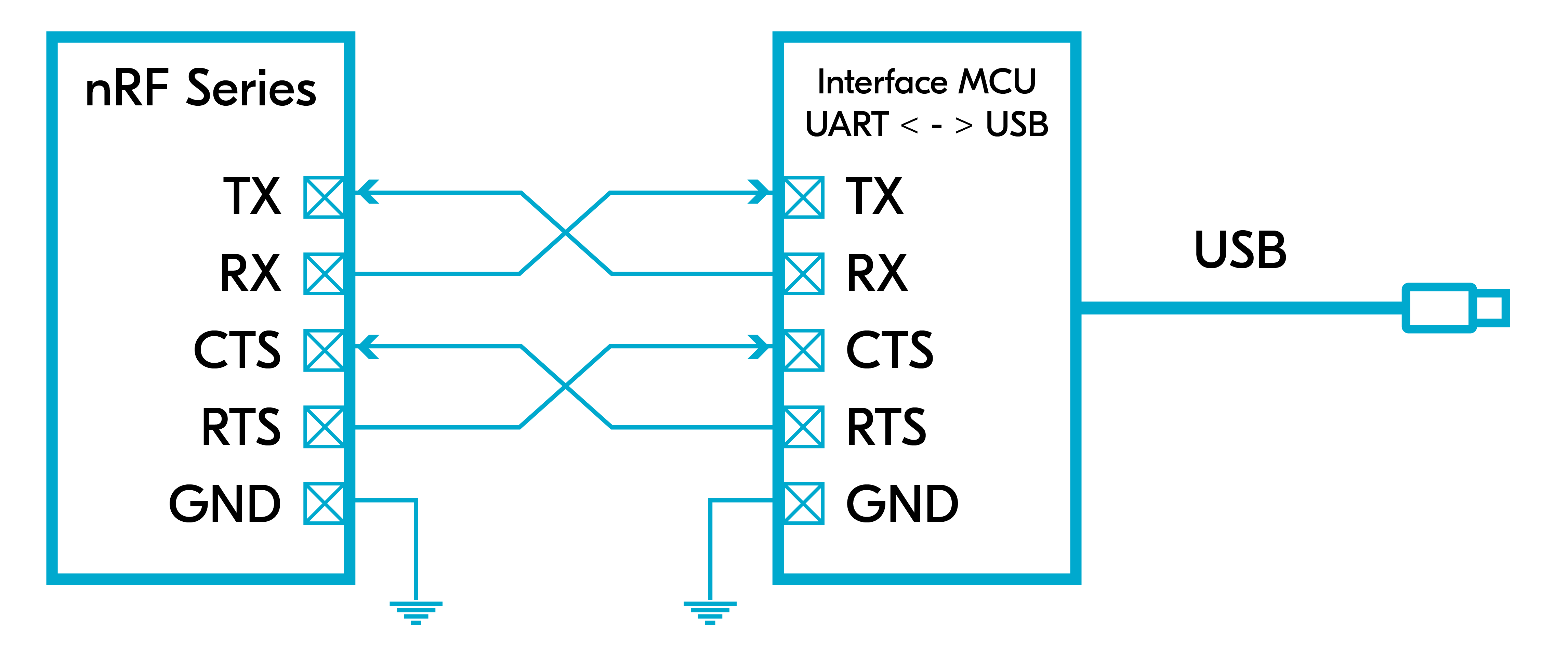
In the exercise, you will learn how to control the LEDs on your development kit through UART. We will utilize the UART controller that is connected by default to the interface MCU on your Nordic development kit to provide UART over USB.
We will set up the UART in asynchronous mode so that a callback function is called every time there is new data. We will set up the receive buffer size to 10 bytes and the receive timeout to 100 microseconds. This means when a byte is received and there is inactivity (no new data) after 100 microseconds, or 10 bytes is received, a UART_RX_RDY event is generated.
In this exercise, we will simply practice the steps covered in the UART Driver section to interact with the UART hardware in an asynchronous manner.
Note
This exercise is not supported on the Thingy (Thingy:53, Thingy:91, Thingy:91 X).
2. Enable the serial driver (UART driver) by adding the following two lines in prj.conf.
Copy
CONFIG_SERIAL=yCONFIG_UART_ASYNC_API=y
Kconfig
As we mentioned before, the first line is usually enabled by default through the board’s devicetree. However, the second line is important to enable the asynchronous API of the serial driver.
3. Include the header file of the UART driver in main.c.
Copy
#include<zephyr/drivers/uart.h>
C
4. Get the device pointer of the UART hardware and verify that it is ready.
4.1 Get the device pointer of the UART hardware.
Remember, in nRF Connect SDK, any peripheral is accessed as a pointer of type struct device.
On the nRF54 Series devices, the peripherals have two digits. In this exercise, we will be using the &uart20 instance.
4.2 Verify that the UART device is ready.
Copy
if (!device_is_ready(uart)){printk("UART device not ready\r\n");return1 ; }
C
5. Get the device pointers of the LEDs through gpio_dt_spec and verify that it is ready.
5.1 Get the device pointer of the LEDs
Since we are using UART to control the LEDs (1-3) on the development kit (this will be LEDs 0-2 on the nRF54 DKs), we need to get the device pointer for these as well. As we saw in Lesson 2, this is encapsulated in the API-specific structure gpio_dt_spec and can be retrieved using GPIO_DT_SPEC_GET().
The nRF7002 DK only has 2 LEDs, so this step requires a different code snippet if you’re using this board.
ret = gpio_pin_configure_dt(&led0, GPIO_OUTPUT_ACTIVE);if (ret < 0) {return1 ; } ret = gpio_pin_configure_dt(&led1, GPIO_OUTPUT_ACTIVE);if (ret < 0) {return1 ; } ret = gpio_pin_configure_dt(&led2, GPIO_OUTPUT_ACTIVE);if (ret < 0) {return1 ; }
C
Copy
ret = gpio_pin_configure_dt(&led0, GPIO_OUTPUT_ACTIVE);if (ret < 0) {return1 ; } ret = gpio_pin_configure_dt(&led1, GPIO_OUTPUT_ACTIVE);if (ret < 0) {return1 ; }
C
7. Define the application callback function for UART. For our simple LED application, we are only interested in the UART_RX_RDY and the UART_RX_DISABLED events related to receiving data over UART. For your own application, this might differ as we discussed in the UART driver section.
With if((evt->data.rx.len) == 1), we are assuming a terminal in char mode, which is the default terminal in nRF Connect for VS Code (nRF Terminal) and PuTTY. These two terminal by default, does not require you to press enter to send the data, hence do not send extra bytes. On the other hand, if you are using a serial terminal in “line mode”, you need to press enter to send the data, which typically sends two extra bytes “/r/n” (Depending on the terminal configuration). Therefore you need to change the condition to match the length of the data you are sending.
8. Register the UART callback function by calling the function uart_callback_set().
Copy
ret = uart_callback_set(uart, uart_cb, NULL);if (ret) {return1; }
C
9. Now let’s send some data over UART.
9.1 Define the transmission buffer, which is a buffer to hold the data to be sent over UART.
staticuint8_t tx_buf[] = {"nRF Connect SDK Fundamentals Course\r\n""Press 1-3 on your keyboard to toggle LEDS 1-3 on your development kit\r\n"};
C
Copy
staticuint8_t tx_buf[] = {"nRF Connect SDK Fundamentals Course\r\n""Press 1-2 on your keyboard to toggle LEDS 1-2 on your development kit\r\n"};
C
Copy
staticuint8_t tx_buf[] = {"nRF Connect SDK Fundamentals Course\r\n""Press 0-2 on your keyboard to toggle LEDS 0-2 on your development kit\r\n"};
C
9.2 Send the data over UART by calling uart_tx(). Since we are not using flow control, pass SYS_FOREVER_US to disable transmission timeout. This is not related to receiving timeout.
Copy
ret = uart_tx(uart, tx_buf, sizeof(tx_buf), SYS_FOREVER_US);if (ret) {return1; }
C
10. Let’s start receiving data!
10.1 Define the receive buffer. For this simple exercise of controlling LEDs through UART, we will define a small buffer of size 10 of type uint8_t.
10.1.1 Define the size of the receive buffer.
Copy
#define RECEIVE_BUFF_SIZE 10
C
10.1.2 Define the receive buffer and initialize its members to zeros.
Copy
staticuint8_trx_buf[RECEIVE_BUFF_SIZE] = {0};
C
10.2 Define the receiving timeout period to be 100 microseconds. This means when a byte is received and there is inactivity (no new data) for 100 microseconds, a UART_RX_RDY event is generated. If you are going to use receive timeout in your application, pick a value that matches your application requirements.
Copy
#define RECEIVE_TIMEOUT 100
C
10.3 Start receiving by calling uart_rx_enable() and pass it the address of the receive buffer.
Copy
ret = uart_rx_enable(uart ,rx_buf,sizeofrx_buf,RECEIVE_TIMEOUT);if (ret) {return1; }
C
11. Build the application and flash it on your development kit.
12. View configuration conflicts.
Now that we’ve built the application, you can go back to the prj.conf file and notice that the first line we added, CONFIG_SERIAL, has a blue squiggly line under it. This indicates a configuration conflict, usually because the Kconfig symbol is set more than once in the active build context.
Hover your mouse over the Kconfig symbol to see the configuration conflict. Here we can see that CONFIG_SERIAL is set more than once in the build.
Go back to the nRF Connect window.
Select the build context for the application (l5_e1), then under the Details view, expand Kconfig. Here we can see all the files that make up the resulting build.
Open the file that matches the build target you are using (in this case the nRF52840 DK)
This is the Kconfig file in the board target definition, zephyr/boards/nordic/
Here we see that CONFIG_SERIAL was enabled in the board’s devicetree.
13. View the Devicetree Visual Editor.
Let’s also check that the UART peripheral was enabled in the devicetree by using the Devicetree Visual Editor.
13.1 Open the Deviceetree Visual Editor.
Select the application image (l5_e1)
Under the ACTIONS view, click on Devicetree.
Alternatively, click on the icon in the left margin to open the Devicetree Visual Editor window.
This will open the Devicetree Visual Editor, which looks like the image below
Context Files: Lists the devicetree file for the active build context (shown in the Build Contexts View).
Context Overview: Lists the devicetree information for the active build context.
Nodes: Lists all available nodes for the selected devicetree file. All changes to nodes and pins here are automatically mirrored in the code of the active devicetree file. The nodes are also represented in the graphical Editor View, which lets you inspect and modify node properties and pin assignments. The graphical Editor View is covered in Lesson 3 in nRF Connect SDK Intermediate.
13.2 Confirm that the UART peripheral has been enabled.
In the Nodes view, find the soc menu and expand it by clicking on the arrow to the right. Then scroll down until you found uart0 and notice that its box has a check mark to indicate that it is enabled in the build context.
Testing
14. You should observe that the three LEDs on your development kit are all switched on. Using a serial terminal such as the integrated nRF Terminal or PuTTY, you should see the below output:
*** Booting nRF Connect SDK ****** Using Zephyr OS ***Press 1-3 on your keyboard to toggle LED 1-3 on your development kit
Terminal
*** Booting nRF Connect SDK ****** Using Zephyr OS ***Press 1-2 on your keyboard to toggle LED 1-2 on your development kit
Terminal
*** Booting nRF Connect SDK ****** Using Zephyr OS ***Press 0-2 on your keyboard to toggle LED 0-2 on your development kit
Terminal
We are using the default baud rate (115200) and UART settings set in the devicetree. If you want to change that, you can do it using the UART API as explained earlier.
Writing a number from 1 to 3 (or 0 to 2 for the nRF54 DKs) in the serial emulator will toggle the corresponding LED on your development kit.
The solution for this exercise can be found in the GitHub repository, l5/l5_e1_sol.
Nordic Developer Academy Privacy Policy
1. Introduction
In this Privacy Policy you will find information on Nordic Semiconductor ASA (“Nordic Semiconductor”) processes your personal data when you use the Nordic Developer Academy.
References to “we” and “us” in this document refers to Nordic Semiconductor.
2. Our processing of personal data when you use the Nordic Developer Academy
2.1 Nordic Developer Academy
Nordic Semiconductor processes personal data in order to provide you with the features and functionality of the Nordic Developer Academy. Creating a user account is optional, but required if you want to track you progress and view your completed courses and obtained certificates. If you choose to create a user account, we will process the following categories of personal data:
Email
Name
Password (encrypted)
Course progression (e.g. which course you have completely or partly completed)
Certificate information, which consists of name of completed course and the validity of the certificate
Course results
During your use of the Nordic Developer Academy, you may also be asked if you want to provide feedback. If you choose to respond to any such surveys, we will also process the personal data in your responses in that survey.
The legal basis for this processing is GDPR article 6 (1) b. The processing is necessary for Nordic Semiconductor to provide the Nordic Developer Academy under the Terms of Service.
2.2 Analytics
If you consent to analytics, Nordic Semiconductor will use Google Analytics to obtain statistics about how the Nordic Developer Academy is used. This includes collecting information on for example what pages are viewed, the duration of the visit, the way in which the pages are maneuvered, what links are clicked, technical information about your equipment. The information is used to learn how Nordic Developer Academy is used and how the user experience can be further developed.
2.2 Newsletter
You can consent to receive newsletters from Nordic from within the Nordic Developer Academy. How your personal data is processed when you sign up for our newsletters is described in the Nordic Semiconductor Privacy Policy.
3. Retention period
We will store your personal data for as long you use the Nordic Developer Academy. If our systems register that you have not used your account for 36 months, your account will be deleted.
4. Additional information
Additional information on how we process personal data can be found in the Nordic Semiconductor Privacy Policy and Cookie Policy.
Nordic Developer Academy Terms of Service
1. Introduction
These terms and conditions (“Terms of Use”) apply to the use of the Nordic Developer Academy, provided by Nordic Semiconductor ASA, org. nr. 966 011 726, a public limited liability company registered in Norway (“Nordic Semiconductor”).
Nordic Developer Academy allows the user to take technical courses related to Nordic Semiconductor products, software and services, and obtain a certificate certifying completion of these courses. By completing the registration process for the Nordic Developer Academy, you are agreeing to be bound by these Terms of Use.
These Terms of Use are applicable as long as you have a user account giving you access to Nordic Developer Academy.
2. Access to and use of Nordic Developer Academy
Upon acceptance of these Terms of Use you are granted a non-exclusive right of access to, and use of Nordic Developer Academy, as it is provided to you at any time. Nordic Semiconductor provides Nordic Developer Academy to you free of charge, subject to the provisions of these Terms of Use and the Nordic Developer Academy Privacy Policy.
To access select features of Nordic Developer Academy, you need to create a user account. You are solely responsible for the security associated with your user account, including always keeping your login details safe.
You will able to receive an electronic certificate from Nordic Developer Academy upon completion of courses. By issuing you such a certificate, Nordic Semiconductor certifies that you have completed the applicable course, but does not provide any further warrants or endorsements for any particular skills or professional qualifications.
Nordic Semiconductor will continuously develop Nordic Developer Academy with new features and functionality, but reserves the right to remove or alter any existing functions without notice.
3. Acceptable use
You undertake that you will use Nordic Developer Academy in accordance with applicable law and regulations, and in accordance with these Terms of Use. You must not modify, adapt, or hack Nordic Developer Academy or modify another website so as to falsely imply that it is associated with Nordic Developer Academy, Nordic Semiconductor, or any other Nordic Semiconductor product, software or service.
You agree not to reproduce, duplicate, copy, sell, resell or in any other way exploit any portion of Nordic Developer Academy, use of Nordic Developer Academy, or access to Nordic Developer Academy without the express written permission by Nordic Semiconductor. You must not upload, post, host, or transmit unsolicited email, SMS, or \”spam\” messages.
You are responsible for ensuring that the information you post and the content you share does not;
contain false, misleading or otherwise erroneous information
infringe someone else’s copyrights or other intellectual property rights
contain sensitive personal data or
contain information that might be received as offensive or insulting.
Such information may be removed without prior notice.
Nordic Semiconductor reserves the right to at any time determine whether a use of Nordic Developer Academy is in violation of its requirements for acceptable use.
Violation of the at any time applicable requirements for acceptable use may result in termination of your account. We will take reasonable steps to notify you and state the reason for termination in such cases.
4. Routines for planned maintenance
Certain types of maintenance may imply a stop or reduction in availability of Nordic Developer Academy. Nordic Semiconductor does not warrant any level of service availability but will provide its best effort to limit the impact of any planned maintenance on the availability of Nordic Developer Academy.
5. Intellectual property rights
Nordic Semiconductor retains all rights to all elements of Nordic Developer Academy. This includes, but is not limited to, the concept, design, trademarks, know-how, trade secrets, copyrights and all other intellectual property rights.
Nordic Semiconductor receives all rights to all content uploaded or created in Nordic Developer Academy. You do not receive any license or usage rights to Nordic Developer Academy beyond what is explicitly stated in this Agreement.
6. Liability and damages
Nothing within these Terms of Use is intended to limit your statutory data privacy rights as a data subject, as described in the Nordic Developer Academy Privacy Policy. You acknowledge that errors might occur from time to time and waive any right to claim for compensation as a result of errors in Nordic Developer Academy. When an error occurs, you shall notify Nordic Semiconductor of the error and provide a description of the error situation.
You agree to indemnify Nordic Semiconductor for any loss, including indirect loss, arising out of or in connection with your use of Nordic Developer Academy or violations of these Terms of Use. Nordic Semiconductor shall not be held liable for, and does not warrant that (i) Nordic Developer Academy will meet your specific requirements, (ii) Nordic Developer Academy will be uninterrupted, timely, secure, or error-free, (iii) the results that may be obtained from the use of Nordic Developer Academy will be accurate or reliable, (iv) the quality of any products, services, information, or other material purchased or obtained by you through Nordic Developer Academy will meet your expectations, or that (v) any errors in Nordic Developer Academy will be corrected.
You accept that this is a service provided to you without any payment and hence you accept that Nordic Semiconductor will not be held responsible, or liable, for any breaches of these Terms of Use or any loss connected to your use of Nordic Developer Academy. Unless otherwise follows from mandatory law, Nordic Semiconductor will not accept any such responsibility or liability.
7. Change of terms
Nordic Semiconductor may update and change the Terms of Use from time to time. Nordic Semiconductor will seek to notify you about significant changes before such changes come into force and give you a possibility to evaluate the effects of proposed changes. Continued use of Nordic Developer Academy after any such changes shall constitute your acceptance of such changes. You can review the current version of the Terms of Use at any time at https://academy.nordicsemi.com/terms-of-service/
8. Transfer of rights
Nordic Semiconductor is entitled to transfer its rights and obligation pursuant to these Terms of Use to a third party as part of a merger or acquisition process, or as a result of other organizational changes.
9. Third Party Services
To the extent Nordic Developer Academy facilitates access to services provided by a third party, you agree to comply with the terms governing such third party services. Nordic Semiconductor shall not be held liable for any errors, omissions, inaccuracies, etc. related to such third party services.
10. Dispute resolution
The Terms of Use and any other legally binding agreement between yourself and Nordic Semiconductor shall be subject to Norwegian law and Norwegian courts’ exclusive jurisdiction.
Switch language?
Progress is tracked separately for each language. Switching will continue from your progress in that language or start fresh if you haven't begun.
Your current progress is saved, and you can switch back anytime.
•This release includes Long-Term Support (LTS) for five years.
•Patch (minor) releases will address security vulnerabilities and critical bug fixes.
•API stability is guaranteed; breaking changes are only introduced when required by a security fix.
•Notifications for critical bug fixes and security updates via the myNordic notification system (mynordic.nordicsemi.com)
General updates
•Support for nRF54LS05 DK (Available through the early access sampling program) •Support for the nRF54LM20B with Axon NPU for Edge AI applications
Bluetooth LE updates
•Quality of Service module is now production-ready. •New experimental features for RF testing (Direct Test Mode) and low-latency packet handling (LE Flushable ACL).
MCUboot & Partition Manager
•Single-Slot DFU and RAM Load mode are both promoted to fully supported •Partition Manager is officially deprecated in favor of Zephyr's devicetree-based partitioning.
General updates
•Added comprehensive support for the nRF54L Series. •Bug fixes and improvements. •Hardware model v1, which was deprecated in nRF Connect SDK 2.7.0, has now been removed. •Multi-image builds functionality (parent-child images), which was deprecated in nRF Connect SDK v2.7.0 has now been removed.
Bluetooth LE updates
•Added support for Bluetooth Core version 6.2. •Added support for Bluetooth LE Shorter Connection Intervals. •Added support for Bluetooth LE Channel Sounding.
Bootloader updates
•Support for MCUboot image compression. •Single slot DFU support for the nRF54L Series. •Encrypted DFU support using ECIES on the nRF54L15, nRF54LM20, and nRF54LV10 SoCs.