The section continues from the previous part, addressing the remaining tests.
Step 3.2 – Bluetooth LE Connection
3.2.1 Press button 1 on the DK. This will put the device in a connectable state. The device will be configured as a Bluetooth LE peripheral, broadcasting connectable advertising. Once it enters the connection state, it will first advertise its presence to nearby central devices through connectable advertising. The connectable advertising contains manufacturer-specific data to make it easy to filter for the device from the central.
Optional: The advertised packets can be examined over the air using Nordic Semiconductor’s simple and affordable Bluetooth LE sniffer. See the Lesson 6—Bluetooth LE sniffer in the Bluetooth LE Fundamentals course lesson. As detailed in the lesson, you will need another device that supports Bluetooth (Nordic Semiconductor’s DK or a Dongle) to perform the sniffing.
Content of the advertising data obtained using Wireshark+nRF Sniffer for Bluetooth LE
3.2.2 Establish a connection to the device. In here, we have three options for the Bluetooth LE central device:
Central as another DK. It runs a central firmware customized for this demo.
Central as a smartphone. It runs the nRF Connect for Mobile app.
Options 2 and 3 represent real-life situations where we don’t have complete control over the connection parameters used in the connection. Option 1, on the other hand, gives us full control over the connection parameters as we have finer Bluetooth LE stack control.
In Bluetooth LE connections, the central device—whether a PC, mobile, or another embedded device—controls connection parameters: connection interval, supervision timeout, and peripheral latency. These are set during the initial connection and can only be modified if the central approves. The peripheral can request updates, but these are treated as suggestions, not commands.
On PCs, the OS Bluetooth stack determines how flexible these settings are. Some allow manual tuning, while others stick to default values. On mobile devices, the operating system (Android or iOS) enforces stricter rules. iOS, in particular, has well-defined limits and will reject any parameter requests that fall outside its guidelines.
On embedded devices, like another DK, we have finer control over the Bluetooth LE stack running on these devices, and hence, we have full control over the connection parameters.
Regardless of the platform, the central always has the final say over connection parameters, and the peripheral cannot enforce changes on its own.
For the used physical layer (PHY), it depends on the capabilities of both ends (central and peripheral). The central or peripheral can request a PHY update after establishing the connection. The devices then negotiate based on their supported PHYs (for example, 1M, 2M or coded). The final PHY is a mutual agreement, not controlled solely by the central.
Use the Programmer app to flash the binary on the other DK , Follow the steps as we did in part 1 ( Step 1.4 – 1.7) to flash the other DK with the central firmware .
Once the central firmware is flashed to the other DK, the four LEDs on that DK will start blinking at a certain interval. The blinking interval represent the state of the device
LED0 – LED3 blinking interval
Status
100 ms
DK is scanning for connectable advertising
1000 ms
DK is in connection with the nRF54L15 DK
3.2.4 The other DK will automatically connect with the nRF54L15 DK . This can be seen by the interval of blinking of the LEDs and is also possible to check through a terminal
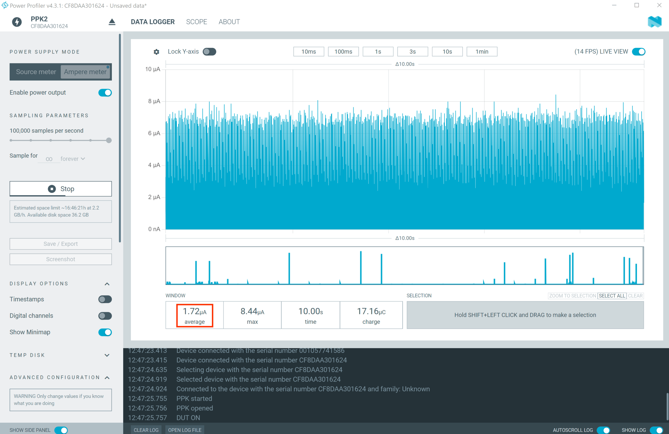
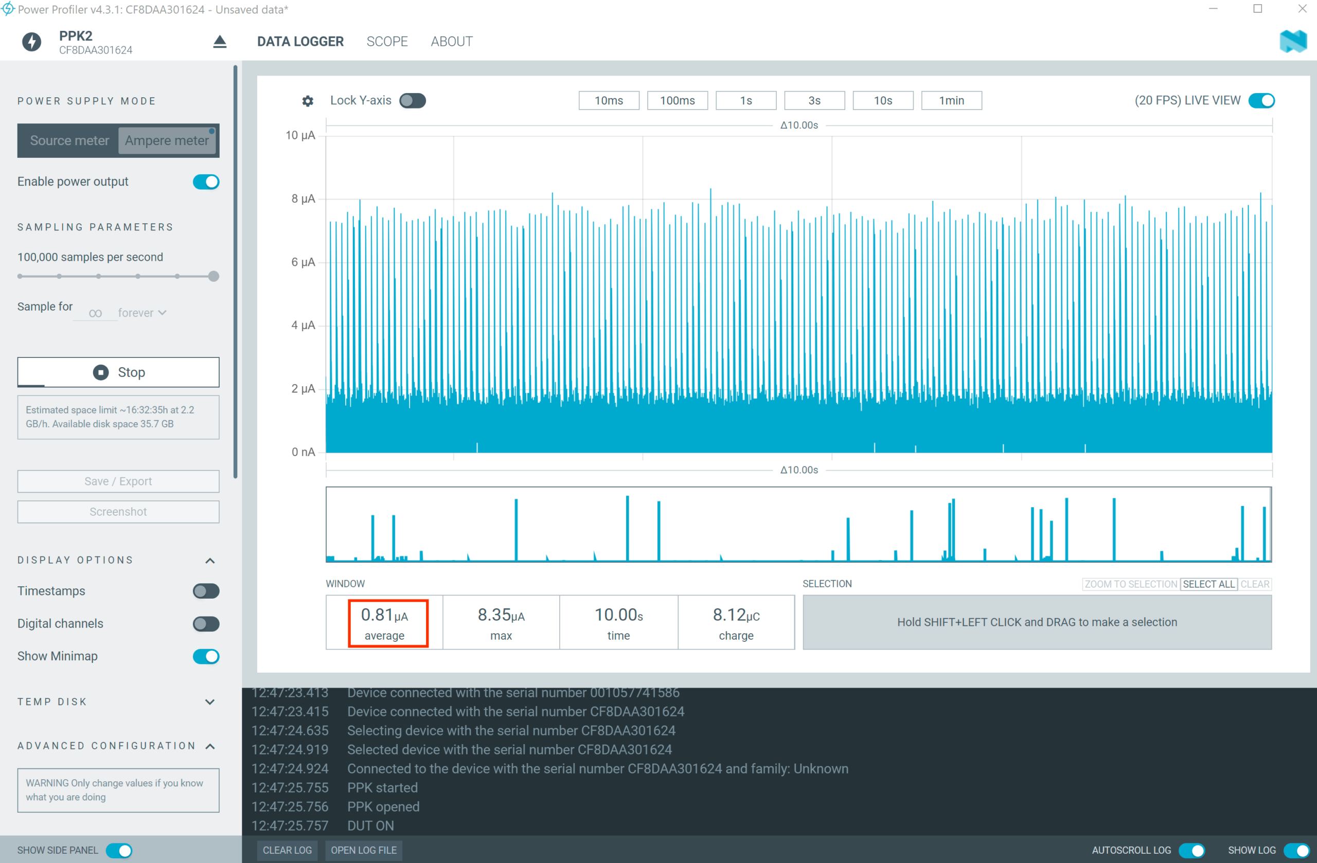
3.2.5 Use the Power Profiler app to see the power consumption needed to maintain the connection with 0 throughput.
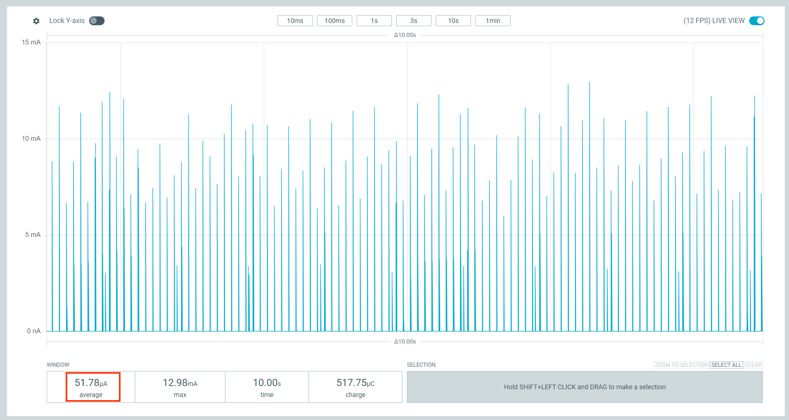
3.2.6 Press button 1 to change the throughput. This will set the low throughput mode (~ 8 kbps).
Same as in the previous step, observe the current consumption on the Power Profiler app. You should see a result around ~ 51 µA.
3.2.7 Press button 1 again to change the throughput. This will set the medium throughput mode (~ 400kbps).
Observe the current consumption on the Power Profiler app. You should see a value around ~1.31 mA:
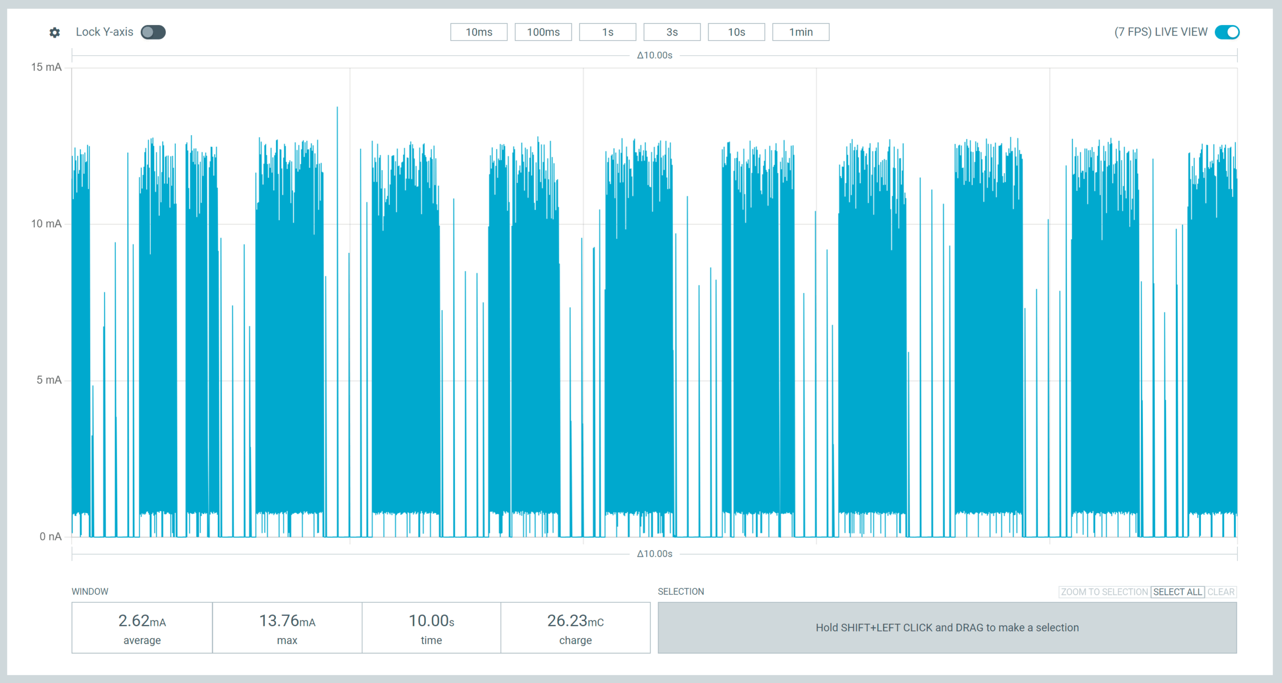
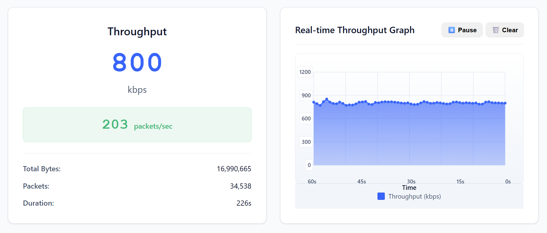
3.2.8 Press button 1 again to change the throughput to high throughput mode (~ 800kbps).
Observe the current consumption on the Power Profiler app. You should see a value around 2.62 mA:
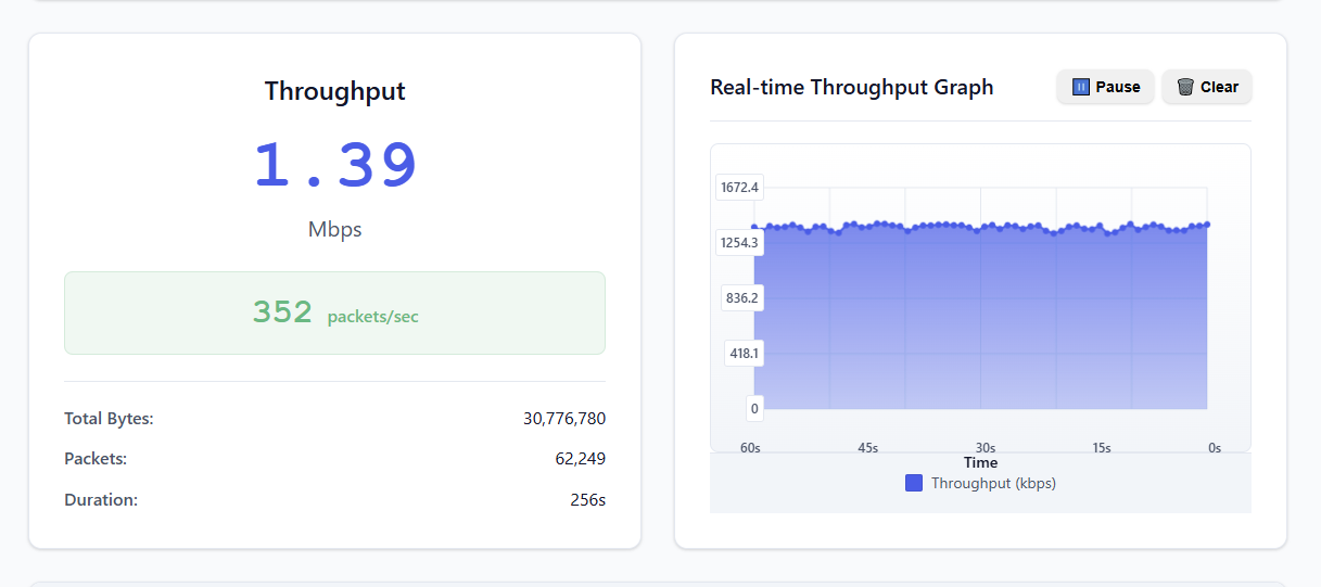
3.2.9 Press button 1 one more time to change the throughput to max throughput mode (~ 1.4Mbps).
Observe the current consumption on the Power Profiler app. You should see a value around ~4.49 mA:
Using a smartphone
With this method, the Bluetooth LE-capable chip on your mobile phone is used as a Bluetooth LE central. While testing, do not perform heavy Bluetooth operations like streaming audio over Bluetooth; otherwise, the throughput numbers will be impacted.
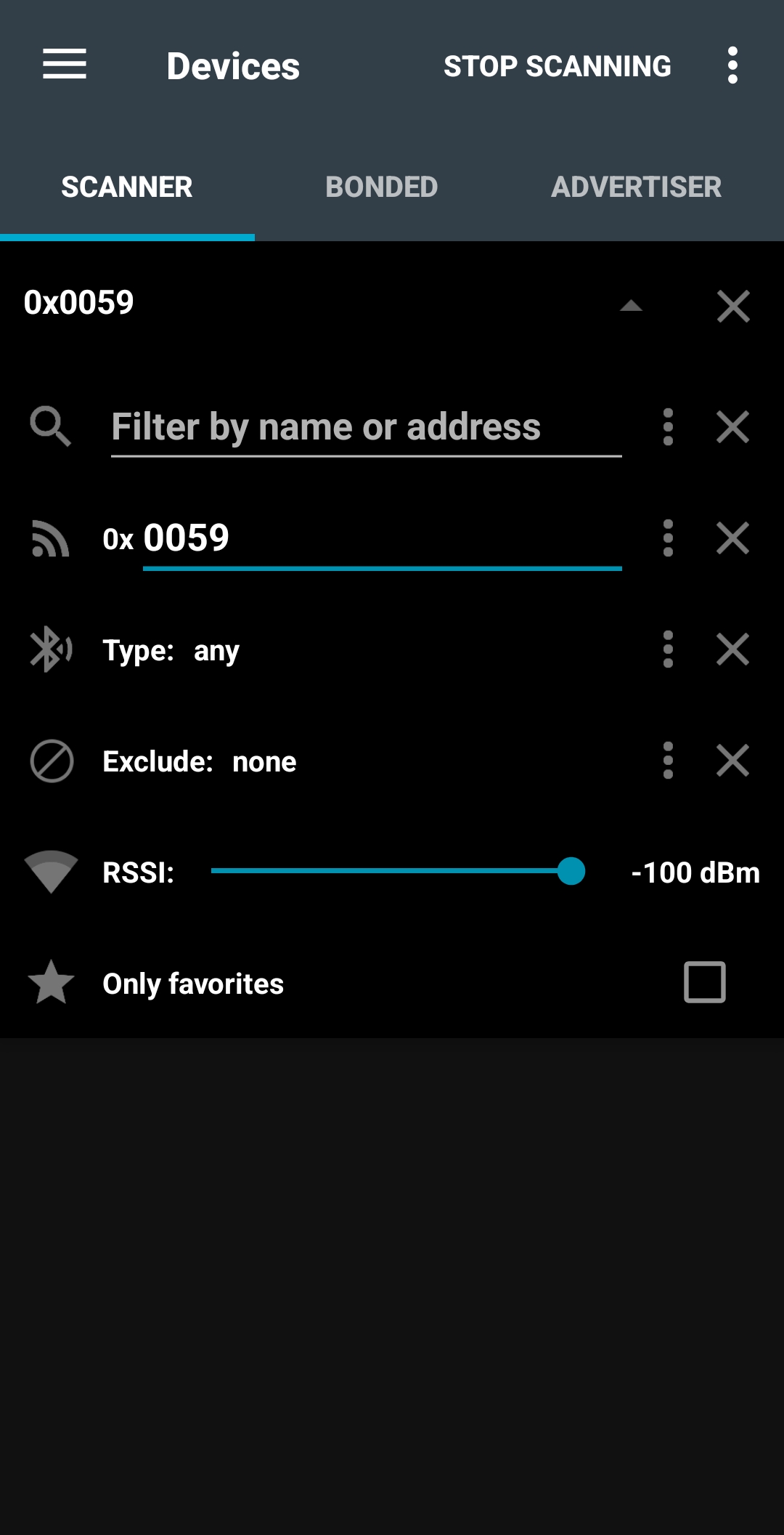
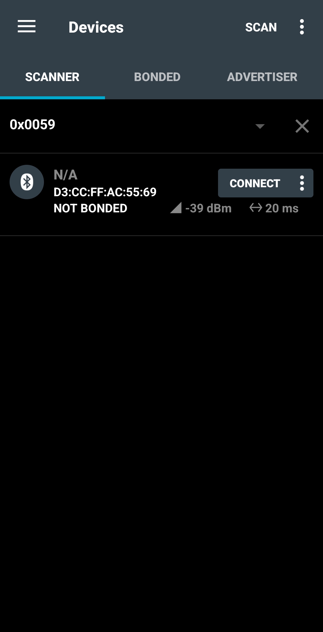
3.2.3 To establish a connection with the device, open nRF Connect for Mobile , From the SCANNER tab, filter by raw advertising data of 0x0059, then press SCAN
Filter by raw advertising data – Android
This will filter advertising devices and only list devices that advertise with the specified data in the packet.
Found device – Android
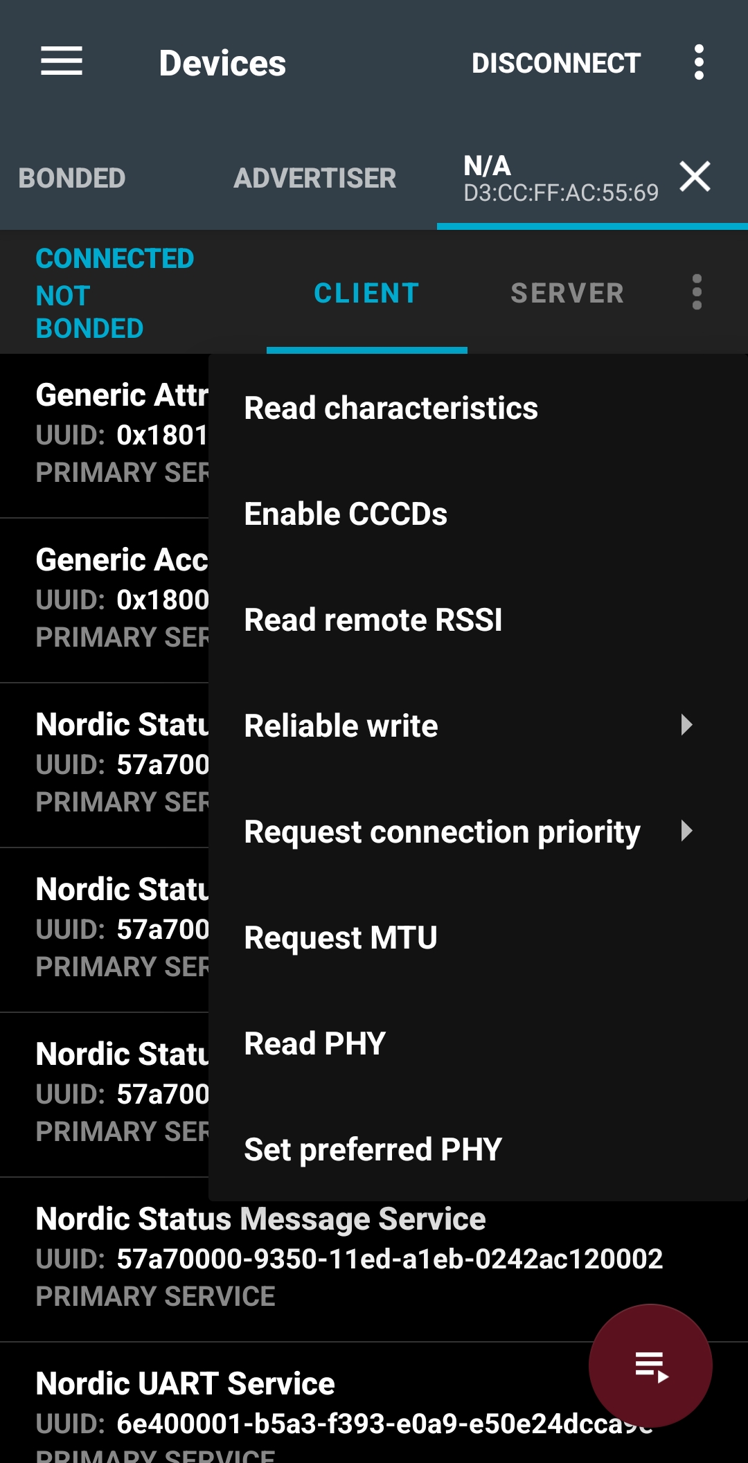
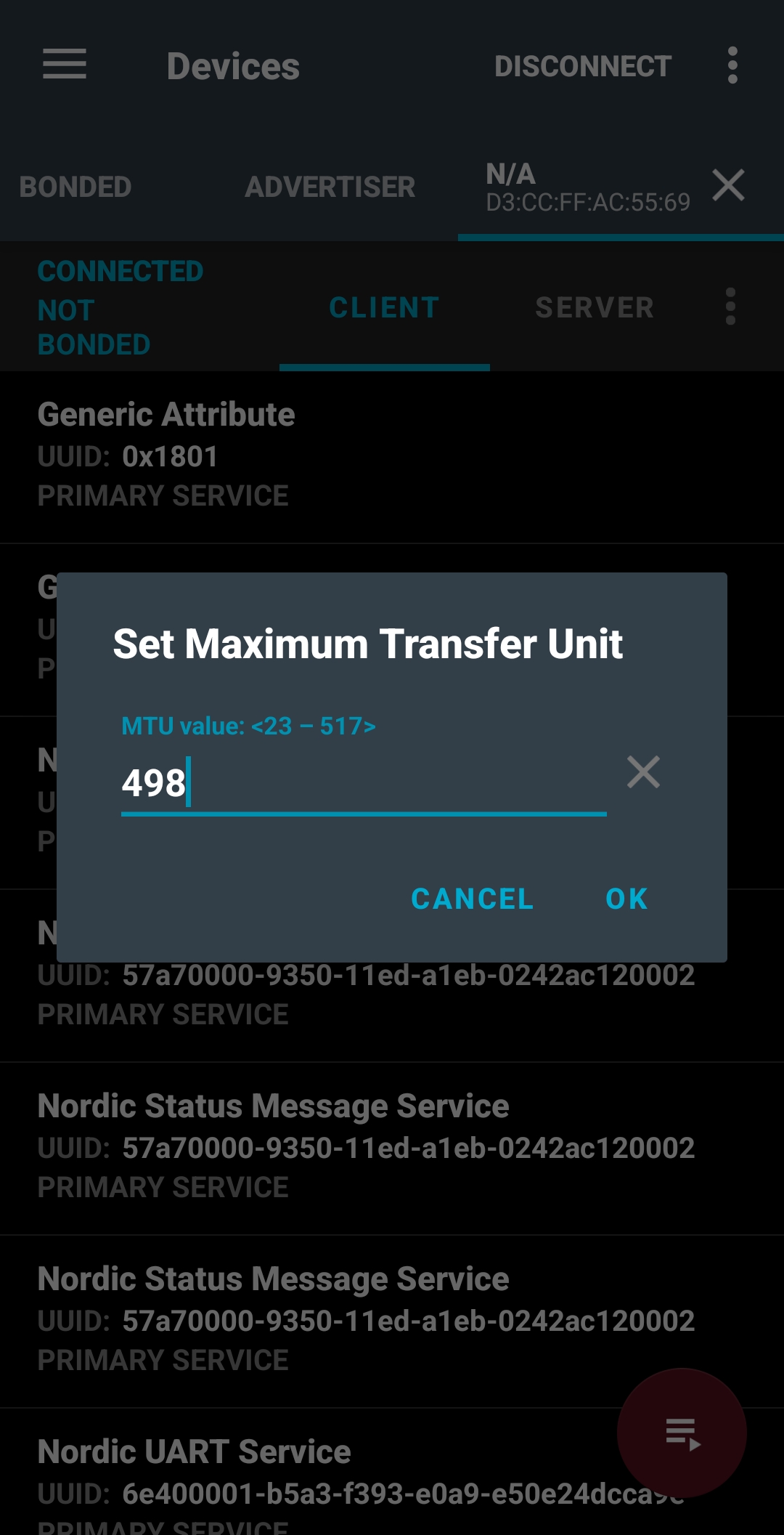
Click on CONNECT to connect to the DK. Once connected, click on the three-dot symbol to open the menu to Request MTU. Type in 498 (this value is the maximum possible on most Android devices).
Open connection menu – AndroidRequest MTU – Android
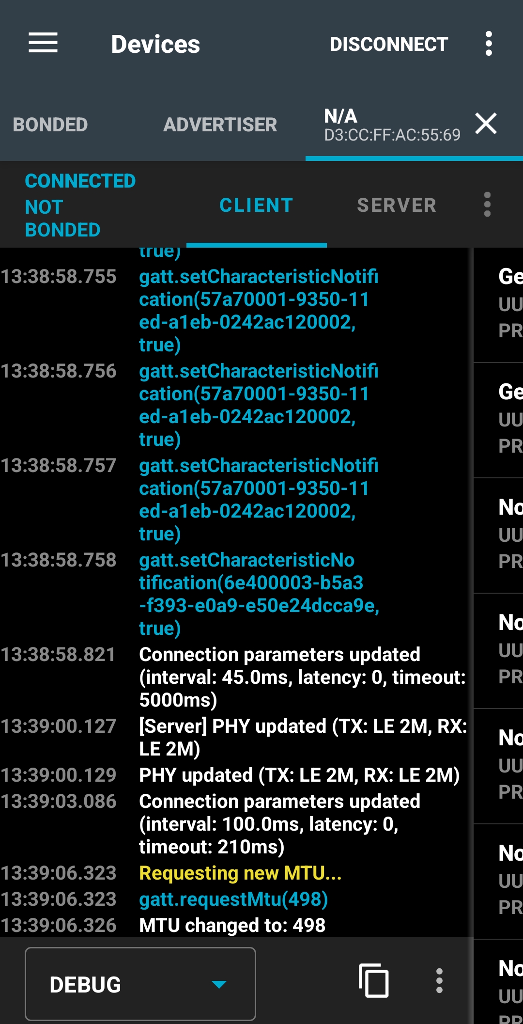
You can always swipe to the right to get the logs of the connection, as shown below:
Accessing logs – Android
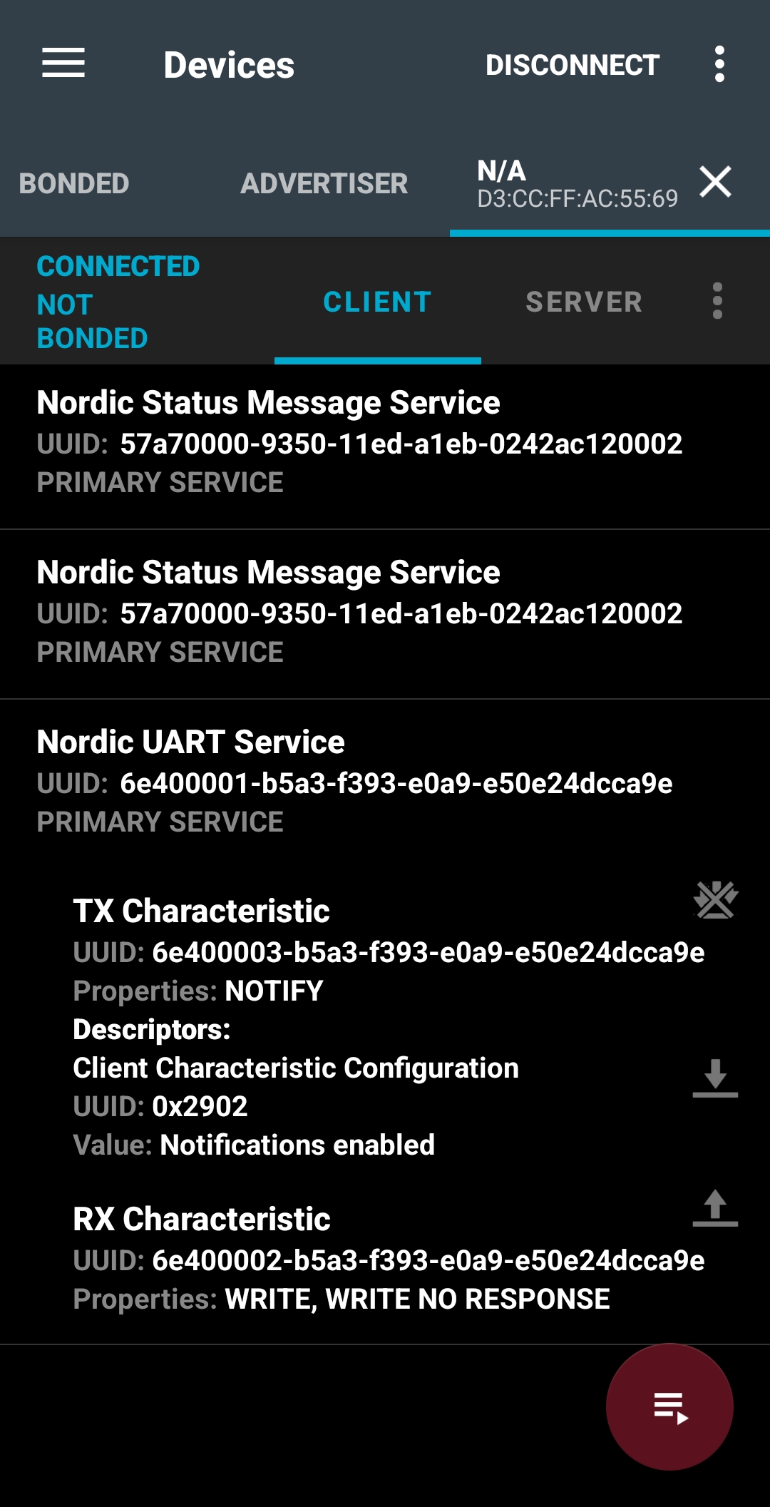
After that, subscribe to the Nordic UART Service – TX Characteristic notification by clicking on the three arrow symbol next to it. This is where we get the data from the development kit.
Subscribe to the Nordic UART Service(NUS) – TX Characteristic notification
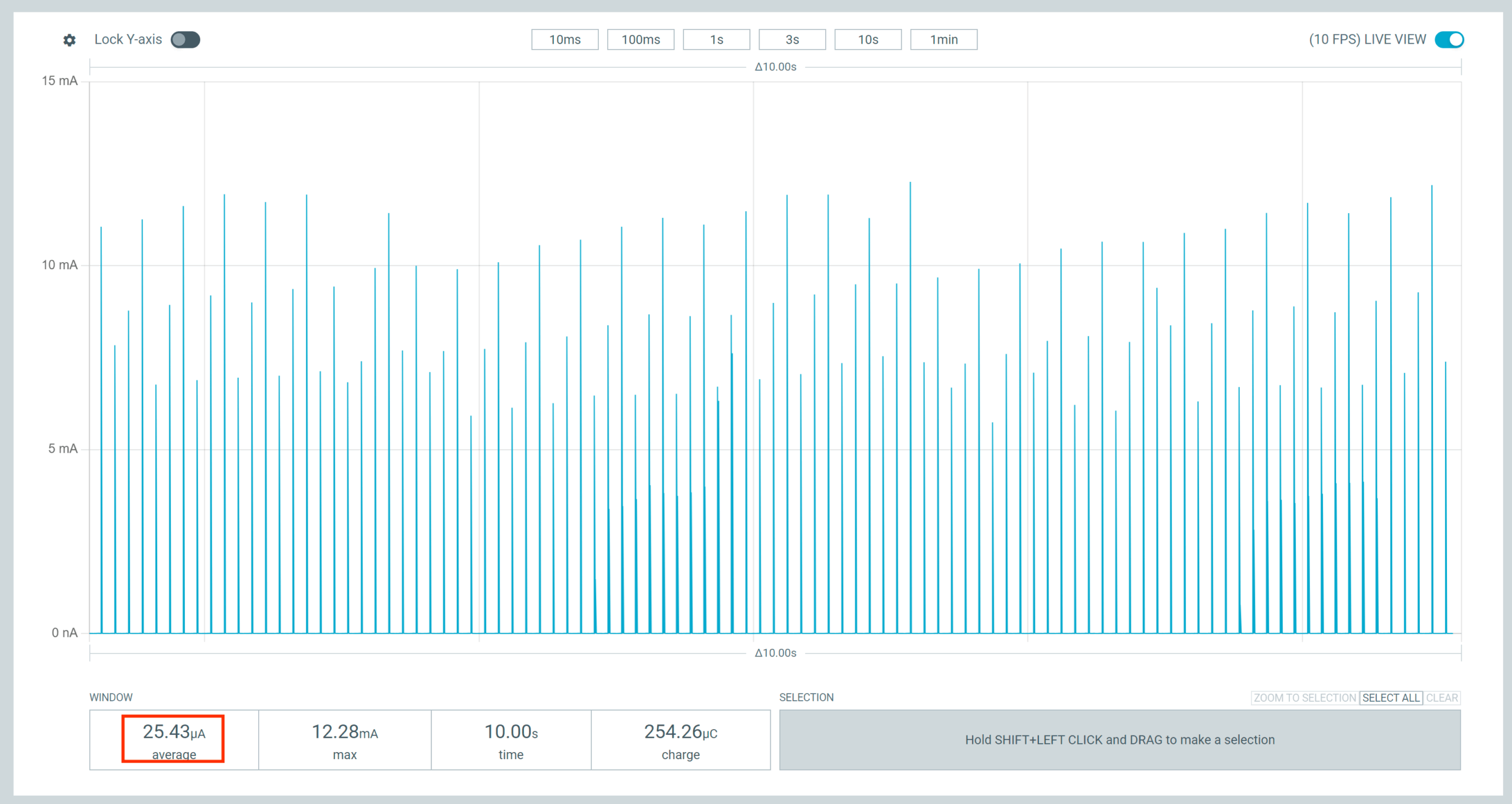
3.2.4 Use the Power Profiler app to see the power consumption needed to maintain the connection with zero throughput; a value of ~ 25 µA is expected. Note that this value will depend heavily on the connection interval agreed upon by the central. It’s possible to change the connection parameters on Android using the nRF Connect for Mobile app by tapping the three-dot menu and selecting Request Connection Priority (High, Balanced, Low Power).
3.2.5 Press button 1 to change the throughput. This will set the low throughput mode (~ 8 kbps). You could swipe to the right in nRF Connect for Mobile to see the content of the packets received.
As in the previous step, observe the current consumption of the Power Profiler app. You should see a result around ~ 51 µA. Again, this number will depend on the connection parameters set by the central.
3.2.6 Press button 1 again to change the throughput. This will set the medium throughput mode (~ 400kbps; the exact number will vary depending on the central).
Observe the current consumption on the Power Profiler app. You should see a value around ~1.31 mA.
3.2.7 Press button 1 again to change the throughput to high throughput mode (~ 800kbps).
The exact number will vary depending on the central, and it may not be achievable on some old mobile devices.
Observe the current consumption on the Power Profiler app. You should see a value around ~2.62 mA.
3.2.8 Press button 1 one more time to change the throughput to max throughput mode (~ 1.4Mbps). The exact number will vary depending on the central, and it may not be achievable on some old mobile devices.
Observe the current consumption on the Power Profiler app. You should see a value around ~4.49 mA.
Using the web app
With this method, the Bluetooth LE-capable chip on your computer is used as a Bluetooth LE central. While testing, do not perform heavy Bluetooth operations like streaming audio over Bluetooth; otherwise, the throughput numbers will be impacted.
We will use the Bluetooth LE Throughput Monitorweb application. The web app is a simple JavaScript that uses the Web Bluetooth API to scan and connect with the DK. It subscribes to the NUS characteristic, parses the received packets, and measures the connection’s throughput. Note that the Web Bluetooth API is compatible with a few browsers; you can check the full browser compatibility table.
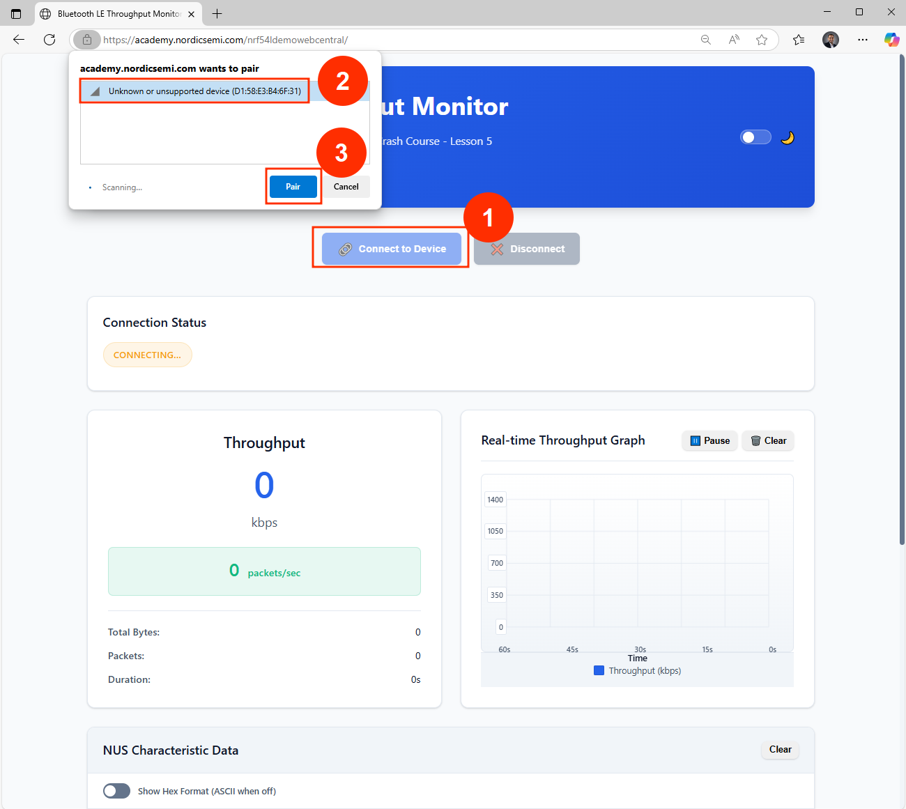
3.2.3 To establish a connection with the device, use the web app (hosted: https://academy.nordicsemi.com/nrf54ldemowebcentral/, also available to run locally in the GitHub repo) and click on the ”Connect to Device” button. Note that the web tool will filter and display only the compatible device advertising the custom manufacturer data.
Connecting to the DK using the web app
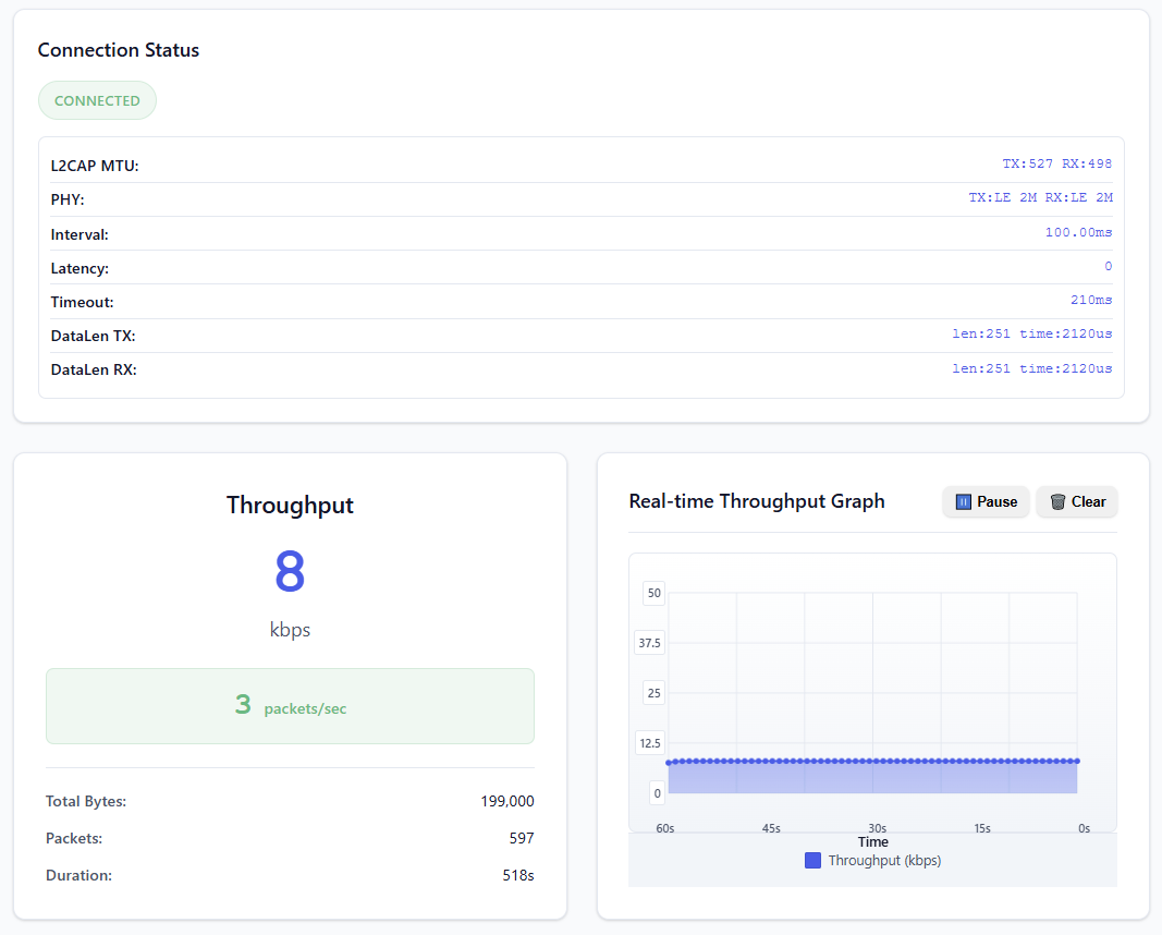
You should see the throughput as zero since the firmware is configured not to send data immediately. After 6 seconds, the connection parameters details will populate in the Connection Status field.
3.2.4 Use the Power Profiler app to see the power consumption needed to maintain the connection with 0 throughput. Note that this will depend heavily on the connection interval agreed upon by the central; a higher or lower average current number than the one shown below is expected.
3.2.5 Press button 1 to change the throughput. This will set the low throughput mode (~ 8 kbps).
Same as in the previous step, observe the current consumption on the Power Profiler app. You should see a results around ~ 51 µA. Again, the average current will depend on the connection parameters set by the central:
3.2.6 Press button 1 again to change the throughput. This will set the medium throughput mode (~ 400kbps; the exact number will vary depending on the central).
Observe the current consumption on the Power Profiler app. You should see a value around ~1.31 mA:
3.2.7 Press button 1 again to change the throughput to high throughput mode (~ 800kbps).
The exact throughput number will vary depending on the central, and it may not be achievable on some operating systems.
Observe the current consumption on the Power Profiler app. You should see a value around 2.62 mA:
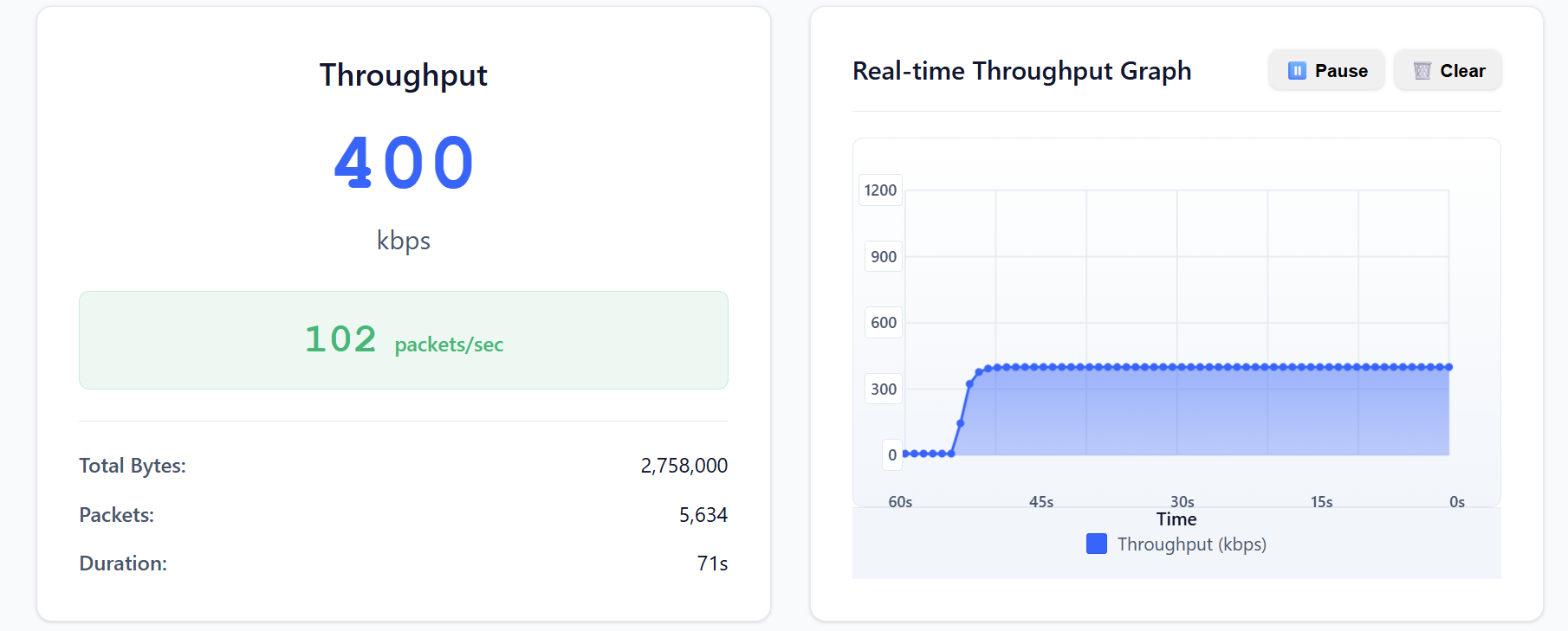
3.2.8 Press button 1 one more time to change the throughput to max throughput mode (~ 1.4Mbps). The exact number will vary depending on the central, and on some operating systems, it is not achievable:
Observe the current consumption on the Power Profiler app. You should see a value around ~4.49 mA:
Step 3.3 – General CPU Processing
In this state, the device engages in intensive computational activity. Every 2.5 seconds, it will solve approximately 1 million quadratic equations and then transition to an idle state. Notably, there is no radio activity during this state, focusing solely on processing power.
3.3.1 Press button 2 to enter the general processing state.
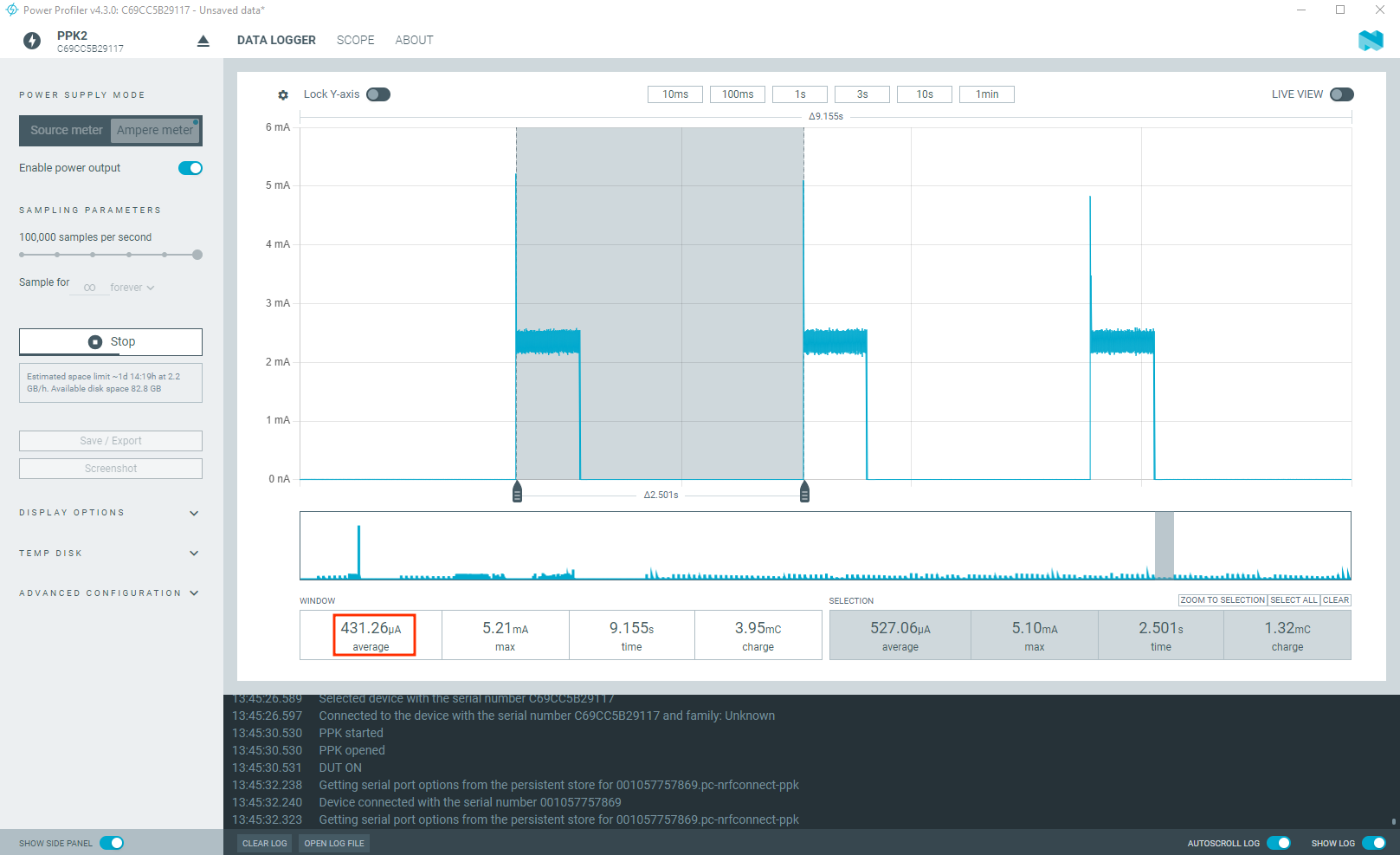
3.3.2 Observe the average current consumption using the Power Profiler. You should see an average current of ~ 431 µA:
Power consumption – general CPU processing
Step 3.4 – System On mode
As we covered in Lesson 3 – Power and clock management, the System ON mode, can operate in either an IDLE or RUN state. The specific state depends on the executing application and also on software configuration. The power and clock management unit dynamically controls internal power domains, switching them on and off based on power requirements, which are tied to the CPU and peripherals’ activity level. When the software has threads that are in a sleeping state and there is no ongoing activity on the peripherals, the device transitions into the System ON-IDLE state. In this state, the expected current consumption is approximately 2.9 µA, as verified during the testing.
In the System ON – IDLE state, we can also control the RAM memory retention. RAM memory retention refers to the ability to preserve the data stored in specific RAM sections. To reduce the overall current consumption, individual RAM sections can be powered off if their content does not need to be retained. For example, in System ON – IDLE current consumption at 3.0 V is ~ 2.9 μA with 256 KB RAM (full memory) retained, but drops to 2.0 μA when only 96 KB RAM is retained. This demonstrates that retaining less RAM directly reduces power. The MEMCONF register gives us full control of the RAM section power and retention. Nordic Semiconductor’s Hardware Abstraction Layer (HAL) provides user-friendly APIs to control this.
3.4.1 Using the Programmer app, flash the binary file mem_ret_192.hex to your development kit. In this firmware binary, we are powering and retaining only 192KB of RAM in System ON – IDLE mode.
3.4.2 Observe the average current in System ON-IDLE mode using the Power Profiler. You should see an average current of approximately 2.6 µA. All the previous functionality is maintained.
System ON-IDLE with 192 KB RAM retention
3.4.3 Using the Programmer app, flash the binary file mem_ret_96.hex to your development kit. In this firmware binary, we are powering and retaining only 96KB of RAM in System ON – IDLE mode.
3.4.4 Observe the average current in System ON-IDLE mode using the Power Profiler. You should see an average current of approximately 2.0 μA. All the previous functionality is maintained.
System ON-IDLE with 96 KB RAM retention
Step 3.5 – System OFF mode
As we covered in Lesson 2, the System OFF mode represents the deepest power-saving state the device can enter. In this state, the device’s core functionality is powered down, and all ongoing tasks are stopped. This mode is ideal for applications requiring the absolute lowest power consumption and can sleep for long periods of time. The nRF54L Series offers the following range of wake-up sources from System OFF:
GPIO DETECT signal
LPCOMP ANADETECT signal
NFCT SENSE signal (wake-on-field)
GRTC SYSCOUNTER compare event
Starting a debug session
Pin reset
You also have the option to retain memory sections in System OFF. In this demo, we set up the device to enter System OFF mode by pressing button 3, which can be exited by pressing any button on the DK (GPIO DETECT signal). Note that the device resets after waking up from System OFF mode, which is completely different from the System On – IDLE mode.
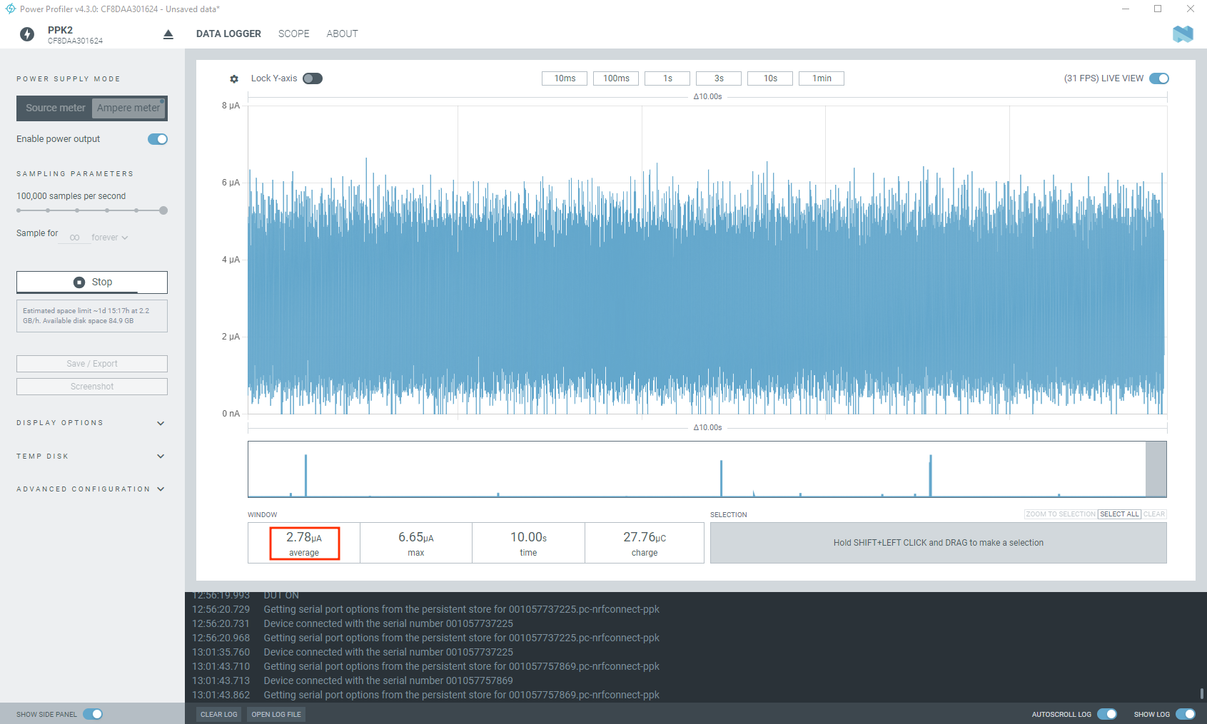
3.5.1 Press button 3 twice to enter System OFF mode. By default, GRTC is kept as a wake-up source (even if you are not using it as one), and no memory is retained.
3.5.2 Observe the average power consumption on the Power Profiler. You should see an average current of ~1.00 uA. By default, GRTC is enabled (even though we are not using it as a wake-up source). If you press any button, the device will wake up from System OFF mode and reset.
System OFF with GRTC & GPIO DETECT signal wakeup
3.5.3 Now let’s disable GRTC as a wake-up source and try to measure the average current in System OFF. Open the Programmer app and flash this binary file systemoff_grtc_off.hex.
3.5.4 Observe the average current consumption using the Power Profiler. You should see a drop of about 0.2 uA from the previous current.
System OFF with GPIO DETECT signal wakeup
Demo source code
The source code for the demo running on the nRF54L Series hardware is located in the demo_app directory of the course repository. The web application source code resides in the web_app directory. The Peer application, located in the peer_app directory, serves as a Bluetooth LE central for connection testing and is compatible with all Nordic Semiconductor’s Bluetooth-LE capable development kits.
Nordic Developer Academy Privacy Policy
1. Introduction
In this Privacy Policy you will find information on Nordic Semiconductor ASA (“Nordic Semiconductor”) processes your personal data when you use the Nordic Developer Academy.
References to “we” and “us” in this document refers to Nordic Semiconductor.
2. Our processing of personal data when you use the Nordic Developer Academy
2.1 Nordic Developer Academy
Nordic Semiconductor processes personal data in order to provide you with the features and functionality of the Nordic Developer Academy. Creating a user account is optional, but required if you want to track you progress and view your completed courses and obtained certificates. If you choose to create a user account, we will process the following categories of personal data:
Email
Name
Password (encrypted)
Course progression (e.g. which course you have completely or partly completed)
Certificate information, which consists of name of completed course and the validity of the certificate
Course results
During your use of the Nordic Developer Academy, you may also be asked if you want to provide feedback. If you choose to respond to any such surveys, we will also process the personal data in your responses in that survey.
The legal basis for this processing is GDPR article 6 (1) b. The processing is necessary for Nordic Semiconductor to provide the Nordic Developer Academy under the Terms of Service.
2.2 Analytics
If you consent to analytics, Nordic Semiconductor will use Google Analytics to obtain statistics about how the Nordic Developer Academy is used. This includes collecting information on for example what pages are viewed, the duration of the visit, the way in which the pages are maneuvered, what links are clicked, technical information about your equipment. The information is used to learn how Nordic Developer Academy is used and how the user experience can be further developed.
2.2 Newsletter
You can consent to receive newsletters from Nordic from within the Nordic Developer Academy. How your personal data is processed when you sign up for our newsletters is described in the Nordic Semiconductor Privacy Policy.
3. Retention period
We will store your personal data for as long you use the Nordic Developer Academy. If our systems register that you have not used your account for 36 months, your account will be deleted.
4. Additional information
Additional information on how we process personal data can be found in the Nordic Semiconductor Privacy Policy and Cookie Policy.
Nordic Developer Academy Terms of Service
1. Introduction
These terms and conditions (“Terms of Use”) apply to the use of the Nordic Developer Academy, provided by Nordic Semiconductor ASA, org. nr. 966 011 726, a public limited liability company registered in Norway (“Nordic Semiconductor”).
Nordic Developer Academy allows the user to take technical courses related to Nordic Semiconductor products, software and services, and obtain a certificate certifying completion of these courses. By completing the registration process for the Nordic Developer Academy, you are agreeing to be bound by these Terms of Use.
These Terms of Use are applicable as long as you have a user account giving you access to Nordic Developer Academy.
2. Access to and use of Nordic Developer Academy
Upon acceptance of these Terms of Use you are granted a non-exclusive right of access to, and use of Nordic Developer Academy, as it is provided to you at any time. Nordic Semiconductor provides Nordic Developer Academy to you free of charge, subject to the provisions of these Terms of Use and the Nordic Developer Academy Privacy Policy.
To access select features of Nordic Developer Academy, you need to create a user account. You are solely responsible for the security associated with your user account, including always keeping your login details safe.
You will able to receive an electronic certificate from Nordic Developer Academy upon completion of courses. By issuing you such a certificate, Nordic Semiconductor certifies that you have completed the applicable course, but does not provide any further warrants or endorsements for any particular skills or professional qualifications.
Nordic Semiconductor will continuously develop Nordic Developer Academy with new features and functionality, but reserves the right to remove or alter any existing functions without notice.
3. Acceptable use
You undertake that you will use Nordic Developer Academy in accordance with applicable law and regulations, and in accordance with these Terms of Use. You must not modify, adapt, or hack Nordic Developer Academy or modify another website so as to falsely imply that it is associated with Nordic Developer Academy, Nordic Semiconductor, or any other Nordic Semiconductor product, software or service.
You agree not to reproduce, duplicate, copy, sell, resell or in any other way exploit any portion of Nordic Developer Academy, use of Nordic Developer Academy, or access to Nordic Developer Academy without the express written permission by Nordic Semiconductor. You must not upload, post, host, or transmit unsolicited email, SMS, or \”spam\” messages.
You are responsible for ensuring that the information you post and the content you share does not;
contain false, misleading or otherwise erroneous information
infringe someone else’s copyrights or other intellectual property rights
contain sensitive personal data or
contain information that might be received as offensive or insulting.
Such information may be removed without prior notice.
Nordic Semiconductor reserves the right to at any time determine whether a use of Nordic Developer Academy is in violation of its requirements for acceptable use.
Violation of the at any time applicable requirements for acceptable use may result in termination of your account. We will take reasonable steps to notify you and state the reason for termination in such cases.
4. Routines for planned maintenance
Certain types of maintenance may imply a stop or reduction in availability of Nordic Developer Academy. Nordic Semiconductor does not warrant any level of service availability but will provide its best effort to limit the impact of any planned maintenance on the availability of Nordic Developer Academy.
5. Intellectual property rights
Nordic Semiconductor retains all rights to all elements of Nordic Developer Academy. This includes, but is not limited to, the concept, design, trademarks, know-how, trade secrets, copyrights and all other intellectual property rights.
Nordic Semiconductor receives all rights to all content uploaded or created in Nordic Developer Academy. You do not receive any license or usage rights to Nordic Developer Academy beyond what is explicitly stated in this Agreement.
6. Liability and damages
Nothing within these Terms of Use is intended to limit your statutory data privacy rights as a data subject, as described in the Nordic Developer Academy Privacy Policy. You acknowledge that errors might occur from time to time and waive any right to claim for compensation as a result of errors in Nordic Developer Academy. When an error occurs, you shall notify Nordic Semiconductor of the error and provide a description of the error situation.
You agree to indemnify Nordic Semiconductor for any loss, including indirect loss, arising out of or in connection with your use of Nordic Developer Academy or violations of these Terms of Use. Nordic Semiconductor shall not be held liable for, and does not warrant that (i) Nordic Developer Academy will meet your specific requirements, (ii) Nordic Developer Academy will be uninterrupted, timely, secure, or error-free, (iii) the results that may be obtained from the use of Nordic Developer Academy will be accurate or reliable, (iv) the quality of any products, services, information, or other material purchased or obtained by you through Nordic Developer Academy will meet your expectations, or that (v) any errors in Nordic Developer Academy will be corrected.
You accept that this is a service provided to you without any payment and hence you accept that Nordic Semiconductor will not be held responsible, or liable, for any breaches of these Terms of Use or any loss connected to your use of Nordic Developer Academy. Unless otherwise follows from mandatory law, Nordic Semiconductor will not accept any such responsibility or liability.
7. Change of terms
Nordic Semiconductor may update and change the Terms of Use from time to time. Nordic Semiconductor will seek to notify you about significant changes before such changes come into force and give you a possibility to evaluate the effects of proposed changes. Continued use of Nordic Developer Academy after any such changes shall constitute your acceptance of such changes. You can review the current version of the Terms of Use at any time at https://academy.nordicsemi.com/terms-of-service/
8. Transfer of rights
Nordic Semiconductor is entitled to transfer its rights and obligation pursuant to these Terms of Use to a third party as part of a merger or acquisition process, or as a result of other organizational changes.
9. Third Party Services
To the extent Nordic Developer Academy facilitates access to services provided by a third party, you agree to comply with the terms governing such third party services. Nordic Semiconductor shall not be held liable for any errors, omissions, inaccuracies, etc. related to such third party services.
10. Dispute resolution
The Terms of Use and any other legally binding agreement between yourself and Nordic Semiconductor shall be subject to Norwegian law and Norwegian courts’ exclusive jurisdiction.
Switch language?
Progress is tracked separately for each language. Switching will continue from your progress in that language or start fresh if you haven't begun.
Your current progress is saved, and you can switch back anytime.